


5-13
ZS-MDC
User’s Manual
Section 5
APPENDIX
Section 5
Index
A
ANALOG 3-17
average height measurement
CALC
3-15
B
Bank switching 3-16
Basic Configuration
1-7
BUSY output
2-11
C
CALC 3-15
Control keys
3-5
Controller Link Unit
Connection
2-5
Specifications and
Dimensions
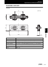
5-11
Coupler
1-9
D
DIGITAL 3-17
E
ENABLE
indicator
1-8
Output
2-11
Extension Cable
5-11
F
Ferrite core
Multi-Controller
2-3
flatness measurement
CALC
3-15
FUN Mode
3-5
H
HIGH
indicator
1-9
Output
2-10
I
I/O cable 2-10
I/O circuit diagrams
2-13
I/O SET
3-16, 3-17
INPUT
3-14
K
K+mX+nY
CALC
3-15
L
Laser indicator 1-8
LCD screen
name
3-5
LD ON
1-8
LOG
3-17
LOW
indicator
1-9
Output
2-10
M
Main Display 3-5
Mode Switch
3-4
Multi-Controller
Attaching the ferrite core
2-3
Installation
2-4
Part Names
1-8
Specifications and
Dimensions
5-6
O
OUT 3-17
OUT0 to 4
2-10
Output cable
2-10
P
PASS
indicator
1-9
Output
2-10
Power supply
1-7
R
RS-232C
cable external
dimensions
5-10
Connector
1-9
RUN mode
3-7
S
SEL CH 3-14
SENSING
3-14
STEP
CALC
3-15
Sub-display
3-5
T
TASK 3-13
TEACH Mode
3-8
THICK
CALC
3-15
Threshold Selector Switch
1-9
Index