


5-3
ZS-MDC
User’s Manual
Section 5 APPENDIX
Section 5
Error Messages and Countermeasures
Error Messages and Countermeasures
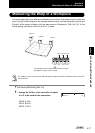
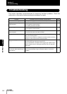
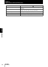
■ When [Error] Is Displayed on the Main Display
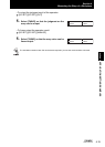
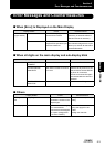
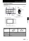
■ When all digits on the main display and sub-display blink
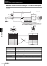
■ Others
Display Details Cause Countermeasure
LCD screen
(upper section)
Overcurrent One or all of the judgment out-
puts are short-circuited.
Cancel the load short-circuit.
(Recovery is automatic after the
load short-circuit is canceled.)
Calculation data error One (or all) of the channels
assigned to the operation input
cannot be measured.
Check the measurement state of
the channels assigned to the oper-
ation input, and set all channels to
a measurable state.
Display Details Cause Countermeasure
LCD screen SYSTEM ERROR
CONNECT
The controller is not connected. Connect the Controller.
SYSTEM ERROR
BANK DATA
Bank data in the Sensor Control-
ler in error
Hold the UP key down for 3 sec-
onds, and then hold the DOWN
key down for 3 seconds.
The sensor is turned ON again
and restored after the device is
initialized.
SYSTEM ERROR
MAIN COM
Internal error Turn the sensor ON again.
Display Details Cause Countermeasure
LCD upper sec-
tion
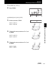
Disp range error The measurement result
exceeds the number of dis-
played digits.
Change the decimal point digit
setting.
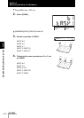
Main Display –– –– – – • The sensor is standing by
for measurement.
• No channels are assigned
to inputs. (Assignments
are set to “NONE”.)
• When hold is set, start sam-
pling and apply the hold
value.
• Assign the channels.