2-10
Section 2 INSTALLATION & CONNECTION
ZS-MDC
User’s Manual
Section 2
About the I/O cable
About the I/O cable
■ Wiring the I/O cable
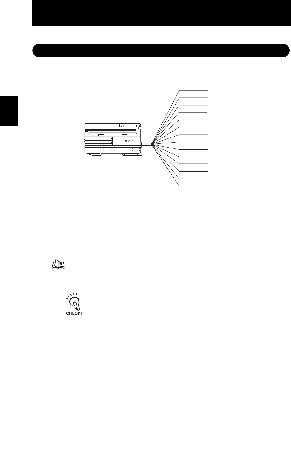
The following shows the leads that comprise the I/O cable.
(1) Power supply
This connects the 24 VDC (±10%) power supply. When using a Multi-Controller with
a PNP output, the power supply terminal is also the common I/O terminal for all I/O
except for the linear output.Supply power from a DC power supply unit that has a
countermeasure (safety ultra-low voltage circuit) built-in for preventing high voltages
from occurring.
Recommended power supply unit p.1-7
Wire the power supply separately from other devices. Wiring them together or placing
them in the same duct may cause induction, resulting in malfunction or damage.
Supply power simultaneously to all gang-mounted controllers to be used.
When power is turned ON individually, the channels will not be recognized normally.
(2) GND
The GND terminal is the 0V power supply terminal. When using a Multi-Controller
with an NPN output, the GND terminal is also the common I/O terminal for all I/O
except for the linear output.
(3) OUT0 (HIGH output)
This outputs judgment results (HIGH).
(4) OUT1 (PASS output)
This outputs judgment results (PASS).
(5) OUT2 (LOW output)
This outputs judgment results (LOW).
(1) Power supply
(3) OUT0
(4) OUT1
(5) OUT2
(6) OUT3
(7) OUT4
(8) Linear output
(9) Linear GND
(10) IN0
(11) IN1
(12) IN2
(13) IN3
(14) Unused
(2) GND
Brown
Blue
Red
Green
Black
Pink
Gray
Co-axial (black)
Shielded
Yellow
Light blue
Purple
White
Orange


