


Section 2 INSTALLATION & CONNECTION
Section 2
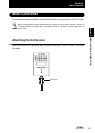
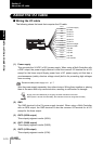
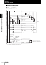
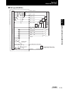
About the I/O cable
2-11
ZS-MDC
User’s Manual
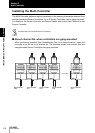
(6) OUT3 (ENABLE output)
This turns ON when the Multi-Controller is ready for measurement. This output is
interlocked with the ENABLE indicator.
(7) OUT4 (BUSY output)
This turns ON during sampling with the hold function enabled. It allows you to check
whether or not the self-trigger is functioning correctly. It also turns ON during bank
switching.
(8) Linear output
The linear output outputs a current or voltage in accordance with the measured
value.
(9) Linear GND
The linear GND terminal is the 0V terminal for the linear output.
This ground wire must be grounded separately from the other ground wires.
Always ground the linear output terminal even when linear output is not used.
(10) to (13) IN0 to IN3
The following input signal assignments can be selected.
• Signal assignments
Setting I/O Assignments p.3-16
• Signal functions
For details on the timing charts of external I/O, refer to User’s Manual for the Sensor Controller.
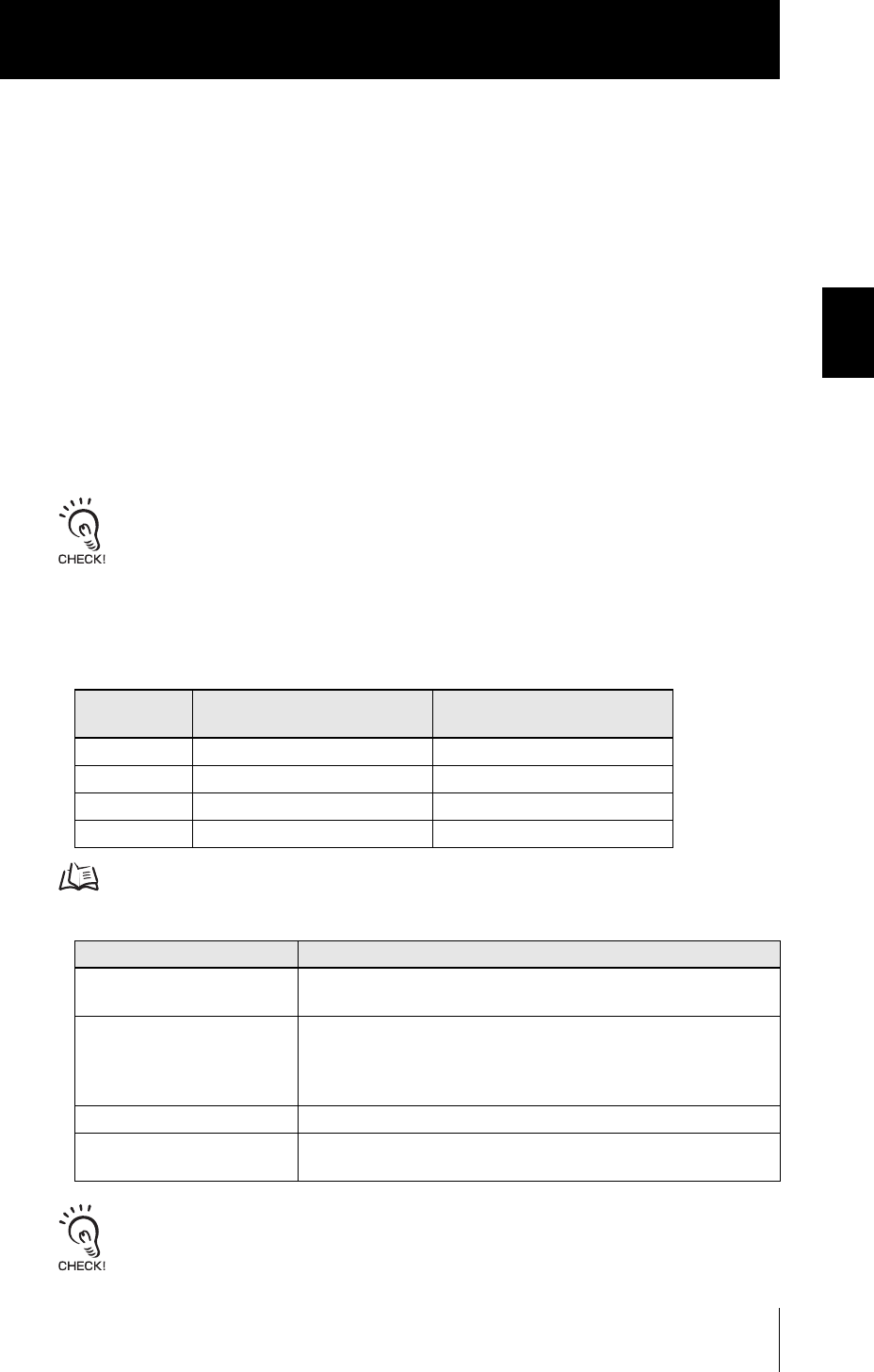
Signal
When [Standard] is selected
(default)
When [Bank] is selected
IN0 External trigger (timing) input Bank input A
IN1 Reset input Bank input B
IN2 Unused Unused
IN3 Zero reset input Zero reset input
Signal Name Description
External trigger (timing) input This timing input is for signal input from external devices. Use it for hold
function timing.
Reset input This resets all executing measurements and outputs. While a reset is
being input, judgment output conforms to the non-measurement set-
ting. If this reset input switches ON while the hold function is used, the
state in effect before the hold function was set will be restored.
Zero reset input This is used to execute and clear a zero reset.
Bank input A, B This is used for switching banks. Specify the bank No. in combinations
of A and B.