


5-7
ZS-MDC
User’s Manual
Section 5 APPENDIX
Section 5
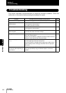
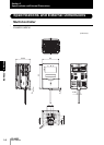
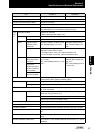
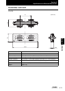
Specifications and External Dimensions
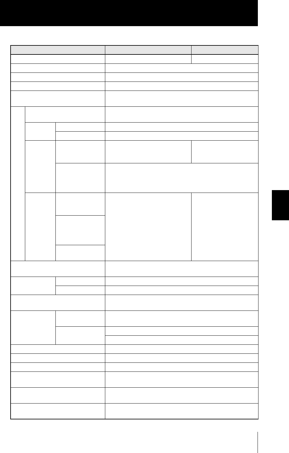
Item ZS-MDC11 ZS-MDC41
I/O type NPNtype PNPtype
No. of samples to average 1, 2, 4, 8, 16, 32, 64, 128, 256, 512, 1024, 2048, or 4096
Number of mounted Sensor Heads Cannot be connected
Connectable version of Sensor Controller Ver2.0 or later
Number of mounted Sensor Controllers Max. 9
(The Controller Link Unit is needed for gang-mounting.)
Exte
rnal
I/F
Connection method Serial I/O or connector
Prewired (standard cable length: 2 m)
Serial I/O USB2.0 1 port, FULL SPEED [12 Mbps], MINI-B
RS-232C 1 port, max. 115200 bps
Output Judgment output
3 outputs: HIGH/
PASS/LOW
NPN open-collector, 30 VDC, 50 mA
max. residual voltage; 1.2 V max.
PNPopen-collector 50 mA
max. residual voltage;1.2V
max.
Linear output Selectable from voltage/current
(selected by slide switch on base)
• At voltage output: -10 to +10 V, output impedance: 40
• At current output: 4 to 20 mA, max. load resistance: 300
Input ZERO reset input
ZERO reset execu-
tion/cancel
ON: Short-circuited with 0V terminal
or 1.5 V max.
OFF: Open (leakage current: 0.1 mA
max.)
ON: Supply voltage short-cir-
cuited or within supply volt-
age -1.5 V
OFF: Open (leakage current:
0.1 mA max.)
Timing input
Sample cycle speci-
fied when hold func-
tion is enabled
RESET input
Reset of hold state
Status indicators HIGH (orange), PASS (green), LOW (orange),
LDON (green), ZERO (green), ENABLE (green)
Segment display Main display 8-segment red display, 6 digits
Sub-display 8-segment green display, 6 digits
LCD 16 digits x 2 rows, color of characters: green, resolution per charac-
ter: 5 x 8 pixel matrix
Setting input Setting keys Direction keys (UP/DOWN/LEFT/RIGHT), SET key, ESC key,
MENU key, function keys (1 to 4)
Slide switch Threshold switch (H/L 2-state)
MODE switch (FUN/TEACH/RUN 3-state)
Power supply voltage 21.6 V to 26.4 V (including ripple)
Current consumption 0.5 A max.
Insulation resistance Across all lead wires and controller case: 20 M (by 250 V megger)
Dialectic strength Across all lead wires and controller case, 1000 VAC, 50/60 Hz, 1
min
Noise immunity 1500 V peak-to-peak, pulse width 0.1 µs/1 µs, rising edge: 1 ns
pulse
Vibration resistance (destructive) 10 to 150 Hz, 0.7-mm double amplitude, 80 min each in X, Y, and Z
directions