


GEK–91584D, Vertical Drilling Motor, Type GE752
12
Brushes
Brush wear is determined by measuring actual brush
length from the top of the carbon. Lift the brush spring,
remove the brush and measure brush length on the
longest side.
NOTE: If brush replacement is not required, be
sure that brushes are of sufficient length to last
until the next inspection.
If one or more brushes are worn to or near the mini-
mum length listed in the DATA section it is generally rec-
ommended that all twelve brushes be replaced at the
same time.
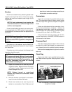
WARNING: To avoid possible electrical shock or
injury from rotating equipment, do not remove or
replace brushes while equipment is energized or
rotating.
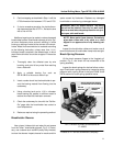
If brushes are to be replaced, see the BASIC RE-
PAIRS, Brush Replacement section for brush installa-
tion instructions.
If brushes are not to be replaced, the following brush
inspection should be made:
CAUTION: When replacing brushes, use only the
GE recommended grade. Mixing of brush grades
in the same motor or changing brushes to anoth-
er grade may seriously affect commutation, sur-
face film, commutator and brush life. See the
DATA section for brush grade.
1. Inspect all brushes to be sure they are not
chipped or broken. Make sure brush shunts are
not frayed or broken. Replace any brush which
shows damage of any kind.
NOTE: Chipped, burned or rough–faced
brushes may indicate the commutator needs
resurfacing.
2. Move the brushes up and down in their carbon-
ways to be sure brushes slide freely.
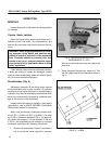
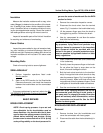
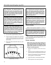
3. Check brush shunts to be sure they are not
twisted or out of position, Fig. 6. Make sure all
brush–shunt terminal connections and all brush-
holder cable connections are tight.
Commutator
Inspect the commutator for possible flashover dam-
age. The commutator should be clean, smooth, glossy
and free of high mica, high bars, flat spots or rough sur-
faces.
If there are indications that the commutator is out–
of–round (as evidenced by variations in width of the
ridge between brush paths), check the concentricity of
the commutator with a dial indicator. Condemning limits
for concentricity are listed in the DATA section.
If the commutator requires grinding, refer to Com-
mutator Resurfacing in the BASIC REPAIRS section of
this manual for instructions.
Creepage Band
Clean the creepage band (located on the commuta-
tor cap) with a clean cloth dipped in an approved sol-
vent. Inspect the band for possible flashover damage.
Make sure the creepage band is tight on the commu-
tator cap.
Flash Ring
Examine the flash ring for possible flashover dam-
age. Wipe the flash ring clean. Keep ring free of dirt and
varnish.
KEEP SHUNTS CLEAR
OF LEVER ARMS
BRUSH
SHUNTS
FIG. 6. CORRECT POSITION OF BRUSH
SHUNTS. E–22568.