


GEK–91584D, Vertical Drilling Motor, Type GE752
64
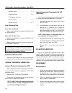
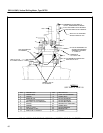
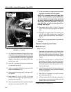
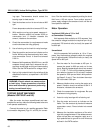
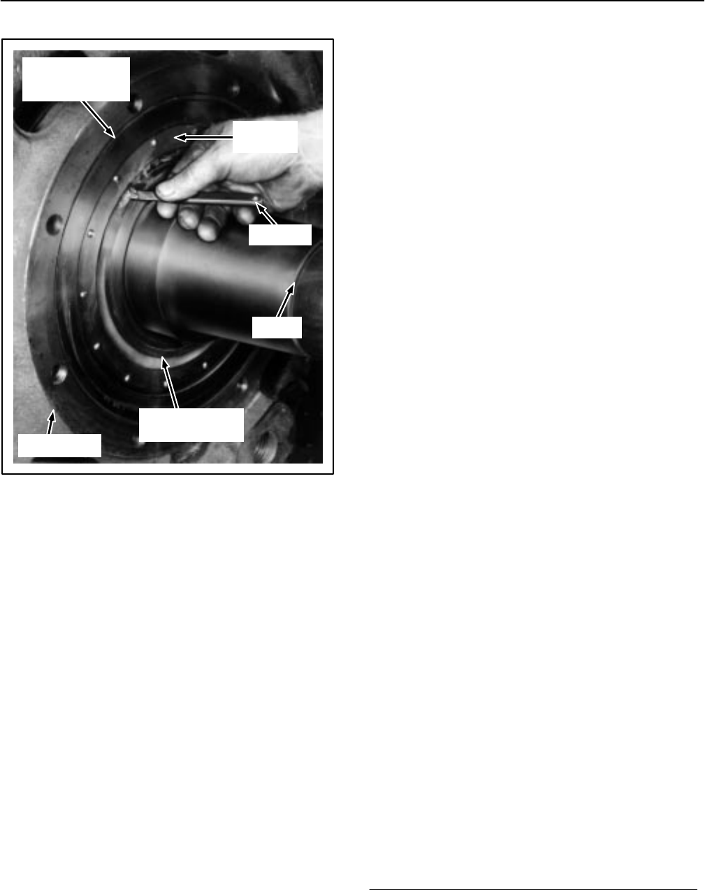
OUTER BEARING
RACE WITH
ROLLERS
BEARING
CAGE
INNER BEARING
RACE
FRAMEHEAD
SHAFT
FEELERS
FIG. 40. CHECKING INTERNAL CLEARANCE OF
BEARING. A-120403.
11. The clearance between the rollers and the inner
race should measure between 0.0012 and 0.004
in. Try various gauge thicknesses until clearance
can be determined by the feel of the gauge as the
gauge is slowly pulled from between the roller
and the inner race.
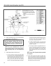
12. Pack 4.8 oz. of grease in the outer circumference
of outer bearing cap (5).
13. Install a new gasket (54) and bearing cap (5) with
bolts and lockwashers (53).
14. Smear seals on bearing cap (5) and sleeve (47)
with grease.
15. Heat sleeve (47) to 110_ C (230_ F) rise and
shrink it onto the shaft tight against the roller
bearing inner race (48).
16. Seal the grease tubes which protrude through
the hole in the frame with RTV–108.
17. At the commutator end, smear the seals on bear-
ing cap (4) and sleeve (42) with grease.
NOTE: Prior to heating sleeve (42), apply NAL-
CO RC* “Rail Conditioner” to the inside diame-
ter of the sleeve and to the mating surface on
the shaft. Apply the NALCO with a Scott–150
white paper towel only and allow it to dry to a
thin white film on both surfaces before pro-
ceeding with Step 18.
18. Heat sleeve (42) to 180_ C (356_ F) rise and
shrink it onto the shaft tight against the spacer
(43).
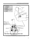
19. Assemble the grease tubes to the bearing cap
(4) (UP1 and AUP1 models only). Install pipe
plugs in tubes and tube fittings as indicated in
Fig. 15.
NOTE: Insure that grease tubes are packed full
of grease.
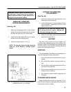
Armature Assembly Into Frame
Models US1, AUT
Refer to Fig. 18.
1. Assemble the brushholders into the frame. Move
them well back from the commutator to avoid in-
terference when installing the armature. Fasten
and insulate the connections and install outgoing
cables.
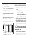
2. Block and level the frame in a vertical position,
commutator–end down, on a heavy duty stand.
Be sure there is clearance for the commutator–
end shaft extension when the armature is low-
ered into the frame.
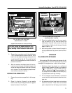
3. Install three guide studs in the commutator–end
bearing housing bolt circle to guide the housing
into the framehead fit.
4. Pack 5.25 oz. of grease in the outer circumfer-
ence of bearing cap (8).
5. Lift the armature with the hoist and lifting bail at
the drive end. Line up the hoist directly over the
center of the cavity in the frame.
*Product of NALCO Chemical Co.