


Vertical Drilling Motor, Type GE752, GEK–91584D
61
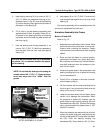
5. Heat bearing housing (2) in an oven to 100_ C
(212_ F). While hot, assemble nilos ring (4) (ori-
ented as shown in Fig. 40), and the ball bearing
(3) into the housing firmly against the shoulder at
the bottom of the bearing fit.
6. Fill all voids in the ball bearing completely with
approximately 20.8 oz. of grease. Smear 0.5 oz.
of grease on the bearing housing and bearing
cap seals, and on the seal ring wear surface on
the nilos ring (4).
7. Heat the bearing and housing assembly in an
oven to 100_ C (212_ F). While hot, assemble it
onto the shaft, with the inner race tight against
sleeve (13).
CAUTION: Be sure that the nilos ring is assembled
over sleeve (13), not pinched between the sleeve
and the bearing.
NOTE: Do not heat the bearing and housing as-
sembly above 100
_
C (212
_
F). Higher tempera-
tures may cause the oil to “bleed” from the
grease.
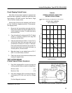
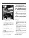
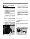
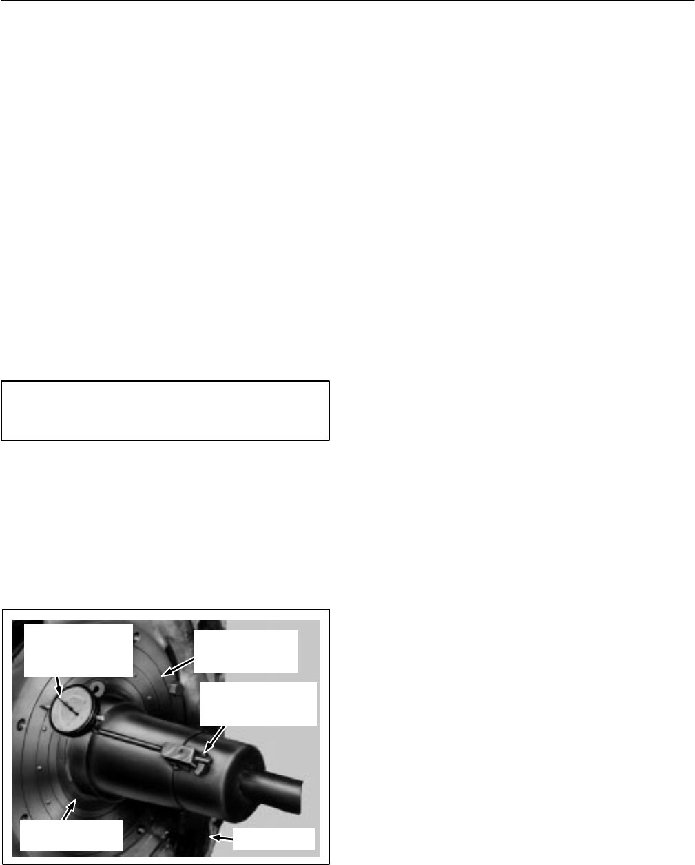
INNER BEARING
RACE
DIAL INDICATOR
POINTER RESTS
AGAINST OUTER
BEARING RACE
FRAMEHEAD
OUTER BEARING
RACE WITH
ROLLERS
SUPPORT FOR
INDICATOR ON
ARMATURE SHAFT
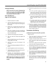
FIG. 37. CHECK ALIGNMENT OF BEARING
AFTER ASSEMBLY. A–120402.
8. Heat spacer (6) to 110_ C (230_ F) and shrink it
onto the shaft tight against the inner race of ball
bearing (3).
The bearing assembly will be completed when the
armature is assembled into the frame.
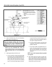
Armature Assembly Into Frame
Models UP and AUP
Refer to Fig. 15.
1. Assemble the brushholders into the frame. Move
them well back from commutator to avoid inter-
ference when installing the armature. Fasten
and insulate the connections and install outgoing
cables.
2. Block and level the frame in a vertical position,
commutator–end down, on a heavy duty stand.
Be sure there is clearance for the commutator–
end shaft extension when the armature is low-
ered into the frame.
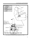
3. Install three guide studs in the commutator–end
bearing housing bolt circle to guide the housing
into the framehead fit.
4. Pack 5.25 oz. of grease in the outer circumfer-
ence of bearing cap (4).
5. Lift the armature with the hoist and lifting bail at
the drive end. Line up the hoist directly over the
center of the cavity in the frame.
6. Lower the armature slowly into the frame, being
careful not to damage the commutator. When
the armature is almost fully inserted, use the
guide studs to align bearing housing (46) and
framehead bolt holes (56). (Position the bearing
cap to accommodate the grease tubes in UP1
and AUP1 models.)
7. When the armature has reached its limit of travel,
remove the guide studs and install bearing cap
(4) with a new gasket (57) using bolts and wash-
ers (52). Draw the bearing housing into
framehead (56). Torque bolts to 105–115 ft.lbs.