


GEK–91584D, Vertical Drilling Motor, Type GE752
20
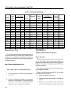
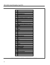
TABLE 2. DRAWING REFERENCE
GE752
Model
Inst.
Book
Longi–
tudinal
Puller Tools
Comm. Pinion
End End
Arm.
Shaft
Connection
Diagram
Coiled
Frame As-
sembly
Bearing Grease
Distribution
Drive Comm.
End End
Arm.
Locking
Arrange-
ment Outline
AUP1 Fig. 15 Fig. 16 Fig. 17 Fig. 20 Fig. 22 Fig. 29 Fig. 34 Fig. 38 Fig. 43 Fig. 48
AUP2 Fig. 15 Fig. 16 Fig. 17 ––– Fig. 22 Fig. 29 Fig. 34 Fig. 38 Fig. 43 Fig. 48
AUP3 Fig. 15 Fig. 16 Fig. 17 ––– Fig. 22 Fig. 29 Fig. 35 Fig. 38 Fig. 43 Fig. 48
AUP4 Fig. 15 Fig. 16 Fig. 17 ––– Fig. 22 Fig. 29 Fig. 35 Fig. 38 Fig. 43 Fig. 48
AUP5 Fig. 15 Fig. 16 Fig. 17 ––– Fig. 22 Fig. 29 Fig. 35 Fig. 39 Fig. 43 Fig. 48
AUT1 Fig. 18 Fig. 16 Fig. 17 ––– Fig. 24 Fig. 32 Fig. 36 Fig. 38 Fig. 43 Fig. 49
AUT2 Fig. 18 Fig. 16 Fig. 17 ––– Fig. 24 Fig. 32 Fig. 36 Fig. 39 Fig. 43 Fig. 49
UP1 Fig. 15 Fig. 16 Fig. 17 Fig. 20 Fig. 21 Fig. 30 Fig. 34 Fig. 38 Fig. 43 Fig. 48
UP2 Fig. 15 Fig. 16 Fig. 17 ––– Fig. 21 Fig. 30 Fig. 34 Fig. 38 Fig. 43 Fig. 48
UP3 Fig. 15 Fig. 16 Fig. 17 ––– Fig. 21 Fig. 30 Fig. 35 Fig. 38 Fig. 43 Fig. 48
UP3A Fig. 15 Fig. 16 Fig. 17 ––– Fig. 21 Fig. 30 Fig. 35 Fig. 38 Fig. 43 Fig. 48
UP4 Fig. 15 Fig. 16 Fig. 17 ––– Fig. 21 Fig. 30 Fig. 35 Fig. 38 Fig. 43 Fig. 48
UP5 Fig. 15 Fig. 16 Fig. 17 ––– Fig. 21 Fig. 30 Fig. 35 Fig. 38 Fig. 43 Fig. 48
UP6 Fig. 15 Fig. 16 Fig. 17 ––– Fig. 21 Fig. 30 Fig. 35 Fig. 39 Fig. 43 Fig. 48
US1 Fig. 18 Fig. 16 Fig. 17 ––– Fig. 23 Fig. 31 Fig. 36 Fig. 38 Fig. 43 Fig. 49
US2 Fig. 18 Fig. 16 Fig. 17 ––– Fig. 23 Fig. 31 Fig. 36 Fig. 39 Fig. 43 Fig. 49
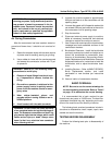
Megohmmeter Test
Lift the brushes and perform a megohmmeter test on
the armature windings and field coils to determine the
condition of the insulation. A reading of less than 2
megohms indicates poor insulation, dirt accumulation or
excessive moisture.
Bar–To–Bar Resistance Test
Test for open or short–circuited armature coils.
1. Pass a regulated d–c current through the arma-
ture coils.
2. Read the voltage drop between the commutator
bars with a millivoltmeter. if the reading varies
more than +/– 5% from the average value, a de-
fective or short–circuited coil is indicated.
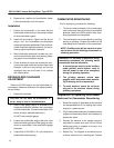
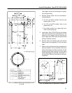
DISASSEMBLY
Armature Removal From Frame
Models UP, AUP
Before turning the machine from horizontal to verti-
cal (or vice–versa), attach the armature locking ar-
rangement to prevent the armature from moving axially.
Remove the armature locking arrangement before op-
erating the machine.
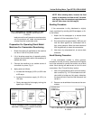
See Table 2 to determine the correct armature lock-
ing arrangement drawing.
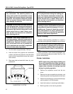
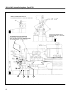
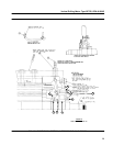
Refer to the longitudinal drawing, Fig. 15, and puller
tool drawings, Figs. 16 and 17.
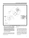
1. Clean the outside of the frame.
2. Remove the hubs from the shaft if not already re-
moved.
3. Remove the commutator covers. Disconnect
and remove all brushes and brushholders. Wrap