


GEK–91584D, Vertical Drilling Motor, Type GE752
14
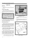
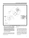
3. Remove bolt, washer and brushholder clamp.
Lift the brushholder out of the frame.
Installation
1. Position the brushholder in the frame with the
brushholder studs resting in the clamp surfaces
of the brushholder support.
2. Install bolt and washer. Tighten bolt but do not
torque until the brushholder–to–commutator
clearance has been established. Refer to Brush-
holder Clearance Adjustment section for instruc-
tions to adjust brushholder clearance.
3. After brushholder clearance has been set, con-
nect the brushholder cable and remove protec-
tive paper from commutator surface.
4. Check brushes to insure they exceed the mini-
mum brush length dimension and are free of any
damage. If they are long enough and are not
damaged, they can be re–used. If not, replace
with new brushes.
BRUSHHOLDER CLEARANCE
ADJUSTMENT
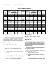
Refer to the DATA section for the brushholder–to–
commutator clearance dimension and adjust brushhol-
der as follows:
1. Remove the brushes.
CAUTION: Do not allow the brushholder to
touch, bump or rest on the commutator.
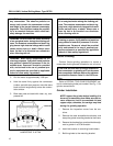
2. Insert a fiber gauge (equal in thickness to the
clearance dimension) between the commutator
and the brushholder. (Loosen brushholder first if
below minimum allowable clearance.)
Do NOT use a metallic gauge.
3. Loosen the brushholder support bolt and move
the brushholder against the fiber gauge so clea-
rance–to–commutator is the same as the gauge
thickness.
4. Torque bolt to 225–250 ft.–lb. and recheck the
brushholder clearance gap.
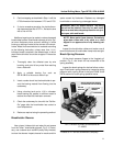
COMMUTATOR RESURFACING
Prior to resurfacing, consider the following:
1. The brush surface diameter of the commutator
must not be less than the minimum permissible
diameter, listed in the DATA section, after resur-
facing operations are completed.
2. The commutator can be resurfaced by sanding,
stoning or grinding. Choose the method to be
used based on the condition of the commutator.
NOTE: Outside power will be required to oper-
ate the motor for the following commutator–re-
surfacing procedure.
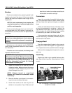
1. A second person must be at the auxiliary
power (welder) control station, ready to
shut off power in case of an emergency
during the grinding operation.
2. The grinding operator should wear
goggles and a dust mask when resurfac-
ing or blowing out the commutator.
3. To avoid electrical shock, do not touch
any part of the machine interior during
grinding operations.
WARNING: For the safety of personnel during
resurfacing operations, the following safety
precautions must be adhered to:
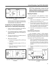
Preparation For Operating Series Model
Machines For Commutator Resurfacing
1. Break the coupling (if applicable) so the machine
can be operated from a d–c welding set or other
outside d–c power source.
2. Lift all the brushes except two of opposite polarity
(adjacent brushholders) which are necessary to
operate the motor.
3. Connect the machine to an outside source of
controlled d–c power; such as a 3–5 kw, 100 vdc
welding set which is capable of driving it at a
speed of 900–1000 rpm.
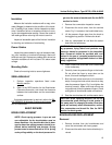
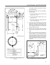
4. Refer to Fig. 7 for diagram of connections to run
a series machine from a welding set. Connect