


GEK–91584D, Vertical Drilling Motor, Type GE752
40
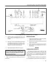
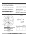
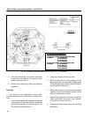
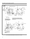
FIG. 22. CONNECTION DIAGRAM (41A237276 CHG. 0). E–39093A.
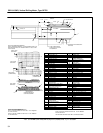
MODELS
SEE TABLE 2
TO CHANGE MOTOR DIRECTION:
TO RUN CCW VIEWED FROM COMMUTATOR END,
CONNECT: F1 TO POSITIVE
F2 TO NEGATIVE
A1 TO POSITIVE
A2 TO NEGATIVE
TO RUN CW VIEWED FROM COMMUTATOR END,
CONNECT: F1 TO NEGATIVE
F2 TO POSITIVE
A1 TO POSITIVE
A2 TO NEGATIVE
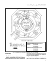
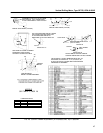
TO CHANGE MOTOR DIRECTION:
TO RUN CCW VIEWED FROM COMMUTATOR END,
CONNECT: F1 TO POSITIVE
F2 TO NEGATIVE
A1 TO POSITIVE
A2 TO NEGATIVE
TO RUN CW VIEWED FROM COMMUTATOR END,
CONNECT: F1 TO NEGATIVE
F2 TO POSITIVE
A1 TO POSITIVE
A2 TO NEGATIVE
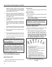
4. Grind the commutator and check commutator
runout with a dial indicator. The maximum com-
mutator runout is 0.001 in.
5. Perform the undercutting, raking and polishing
operations.
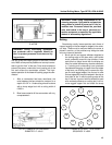
Turning
If the surface of the commutator is badly worn,
burned or scarred, turn the commutator in a lathe as fol-
lows:
1. True the shaft centers with respect to the bearing
fits by scraping. Place the armature in a lathe and
check the concentricity of the bearing fits. The
TIR should not exceed 0.001 in.
2. Cover the windings to keep out chips.
3. Set the cutting tool for turning copper, and set
lathe speed to give a commutator surface speed
of 300 feet per minute. Refer to the DATA section
for dust groove dimensions.
4. Make clean, smooth cuts to remove just enough
copper to renew the commutator surface. Do not
allow the cutting tool to chatter.
5. After turning operations have been completed,
check commutator runout with a dial indicator.
The maximum runout is 0.001 in.
6. Perform the undercutting, raking and polishing
operations.