


Vertical Drilling Motor, Type GE752, GEK–91584D
9
decks by bolting or welding should not require additional
grounding. (References: ABS Rules for Building and
Classing Steel Vessels, Section 35.9.6, and IEEE Stan-
dard 45–1977, Recommended Practice for Electrical In-
stallations on Shipboard, Section 21.4.)
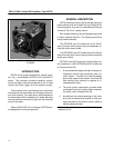
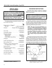
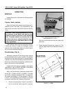
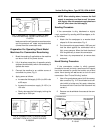
GROUNDING PROCEDURES (Fig. 2)
Most GE drilling machines have extra tap blocks on
the frame for mounting of the connection boxes. One of
these may be used for attaching the grounding cable. If
one is not available, use the lower chain case mounting
boss on the end opposite the drive end in accordance
with Step 2.
1. To attach the ground cable to a tap block, obtain
a 0.75–10 bolt with length of 1.0 to 1.5 in. and a
lockwasher. Also obtain a cable lug to fit the
ground cable and large enough for the 0.75 di-
ameter bolt.
2. To attach the cable to the chain case boss, obtain
a 1.25–7 bolt with length of 1.0 to 1.75 in. and a
lockwasher. Prepare a copper plate at least 1/8
in. thick with a 1.25 in. diameter hole for bolting to
the chain case boss, and with enough extra area
for holes to attach a cable lug. Drill hole(s) in
plate for cable lug. Clean all paint, rust and oil
from the chain case boss and bolt the copper
plate to the chain case boss.
3. Prepare a ground conductor* long enough to run
from the motor frame to an existing ground con-
ductor system or to a suitable equipment ground
point as defined by the National Electrical Code
Article 250 or other applicable regulation. Check
that the system ground detector is also con-
nected to the Common ground point for the rig
and make connection if necessary.
4. Install terminal lugs on cable. Remove paint, rust
and oil from the surfaces to which the cables are
to be attached and bolt the lugs securely to these
surfaces.
*Use 4/0 size or larger copper cable for GE752 ma-
chines. (Reference: National Electrical Code, 1978
Edition, Table 250–95.)
5. Use a digital ohmmeter to check that the bolted
connections are solid, low resistance connec-
tions from the cable conductor to the ground
point and to the motor frame. The meter reading
should be 0.2 ohms or less.
OVERHAUL
Overhaul intervals will depend on the severity of serĆ
vice seen by the machine. However, General Electric
Co. recommends that an overhaul be performed every
18,000 hours (approximately every two years) on all
machines subjected to normal operation.
The motor should be removed, disassembled,
cleaned, inspected and reconditioned as necessary (in-
cluding varnish treatment of armature and fields). Motor
bearings should be repacked with grease. See the
DATA section for grease type and quantity.
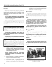
LUBRICATION
Periodic lubrication is required on all GE752 drilling
machines designed for vertical operation between
scheduled overhaul periods. Every six months or 2500
hours, whichever comes first, apply approximately 2 oz.
of grease at each end.
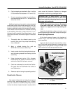
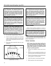
GREASE TUBES AND PIPE PLUGS
The following lists grease tube and pipe plug configu-
rations for all models covered in this publication:
1. UP1 and AUP1 — Four grease tubes with pipe
plugs, two at each end.
2. UP2 and AUP2 — Two grease tubes with pipe
plugs, one at each end.
3. UP3, UP3A, UP4, UP5, UP6, AUP3, AUP4,
AUP5 – One grease tube with a pipe plug at the
drive end, one pipe plug only at the commutator
end.
4. US1, US2, AUT1, AUT2 – One pipe plug only at
each end.
Pipe plugs are provided on bearing caps and on the
ends of all grease tubes to prevent the ingress of dirt or
other contamination.
Remove the pipe plugs and install grease fittings to
facilitate lubrication. Replace the pipe plugs after adding
lubricant. See the DATA section for recommended
grease type.