


Vertical Drilling Motor, Type GE752, GEK–91584D
25
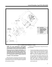
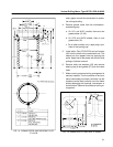
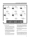
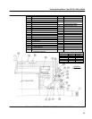
FIG. 16. PULLER TOOLS (41D731569 CHG. 0). E–14383C.
REF DESCRIPTION REF DESCRIPTION REF DESCRIPTION
4 CLAMP PLATE 12 NUT, 5/8–11 21 STUD
5 BOLT 18 RING 22 STUD
6 PRESSURE CAP 20 STUD 23 NUT, 7/16–14
8. Reach into the drive–end of the motor and dis-
connect grease tubes.
a. On UP1 and AUP1 models, disconnect two
grease tubes (21 and 22) from the inner bear-
ing cap (51). Pull these tubes out through
their hole in the frame. The sealing RTV in the
hole will separate with sufficient force.
b. On UP2 and AUP2 models, disconnect one
grease tube (21) from the inner bearing cap
(51). Pull this tube out through its hole in the
frame. The sealing RTV in the hole will sepa-
rate with sufficient force.
c. On all other models, only one grease tube is
used, connected between the inner bearing
cap and the framehead. Remove this tube.
9. Place three 0.125 in. spacers (wedge shaped)
around the armature in the air gap between the
armature and the fields to maintain a vertical atti-
tude of the armature and to prevent the armature
from contacting the fields.
10. Remove bolts (10) and lockwashers (12) from
the framehead (55). Insert bolts into the jackout
holes in the framehead.
11. Install a lifting bail, Fig. 14, onto the end of the
shaft.
12. Line up the hoist cable with the centerline of the
armature before engaging the hook in the lifting
bail on the end of the shaft. Engage the hook and
lift slightly. With sufficient strain on the hoist
cable to take the weight of the armature off the