


Vertical Drilling Motor, Type GE752, GEK–91584D
65
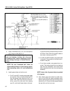
6. Lower the armature slowly into the frame, being
careful not to damage the commutator. When
the armature is almost fully inserted, use the
guide studs to align bearing housing (3) and
framehead bolt holes (14).
7. When the armature has reached its limit of travel,
remove the guide studs and install bearing cap
(8) with a new gasket (11) using bolts and wash-
ers (10). Draw the bearing housing into
framehead (14). Torque bolts to 110–120 ft.lbs.
8. Install framehead bolts and lockwashers(30).
Torque to 440–495 lb.–ft.
CAUTION: Alternate tightening of commu-
tator–end bearing housing and drive–end
framehead bolts. Uneven tightening of bolts
could damage bearings or related fitted sur-
faces.
NOTE: Be sure drive–end framehead bolt holes
are aligned with holes in inner bearing cap be-
fore assembling bolts and lockwashers (30).
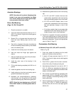
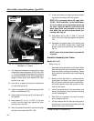
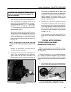
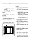
9. Use a feeler gauge and check the radial clear-
ance on the drive–end bearing between each
bearing roller and the inner race, at the top of the
bearing, Fig. 40. Place the feeler gauge between
the top roller and the inner race.
10. The clearance between the rollers and the inner
race should measure between 0.0012 and 0.004
in. Try various gauge thicknesses until clearance
can be determined by the feel of the gauge as the
gauge is slowly pulled from between the roller
and the inner race.
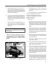
11. Pack 4.8 oz. of grease in the outer circumference
of outer bearing cap (36).
12. Install a new gasket (35) and bearing cap (36)
with bolts and lockwashers (34). Torque bolts to
110–120 ft.lbs.
13. Smear seals on bearing cap (36) and sleeve (37)
with grease.
14. Heat sleeve (37) to 110_ C (230_ F) rise and
shrink it onto the shaft tight against the roller
bearing inner race (38).
15. Finish the assembly of grease tube fittings and
washer (27) where it passes through the
framehead. Tighten all fittings and hardware.
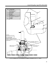
16. At the commutator end, smear the seals on bear-
ing cap (8) and sleeve (6) with grease.
NOTE: Prior to heating sleeve (6), apply NALCO
RC “Rail Conditioner” to the inside diameter of
the sleeve and to the mating surface on the
shaft. Apply the NALCO with a Scott–150 white
paper towel only and allow it to dry to a thin
white film on both surfaces before proceeding
with Step 18.
17. Heat sleeve (6) to 180_ C (356_ F) rise and
shrink it onto the shaft tight against the spacer
(5).
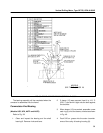
18. Install pipe plugs in grease tubes and tube fit-
tings as indicated in Fig. 18.
NOTE: Insure that grease tubes are packed full
of grease.
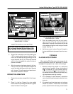
BRUSHHOLDER CLEARANCE
ADJUSTMENT
1. Remove the protective covering from the com-
mutator. Place a 1/16 in. fiber spacer between
the bottom of the brushholder and commutator.
Loosen the brushholder clamp bolts and move
the brushholders so they touch the fiber spacer.
Tighten the clamp bolts to 225–250 lb.–ft. torque
and remove the spacer.
2. Connect the cable leads to the brushholder ter-
minals and tighten the terminal bolts.
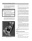
BRUSH INSTALLATION
1. Install new brushes.
CAUTION: When replacing brushes, use only
the GE recommended grade. Mixing of brush
grades in the same motor or changing
brushes to another grade will seriously affect
commutation, surface film, commutator and
brush life. See the DATA section for brush
grade.
2. Carefully lower the spring–loaded brush lever on
each brush. Do not allow the lever to snap
against the brush, as the brush may chip.