


Vertical Drilling Motor, Type GE752, GEK–91584D
57
Armature Bearings
NOTE: Parts that will be shrink–fitted should be
heated in an oven and assembled hot. Make
sure shrink–fitted parts are tight against adja-
cent parts after they have cooled.
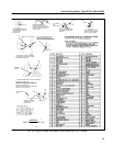
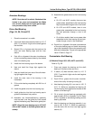
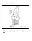
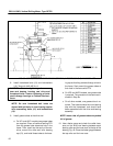
Drive–End Bearing
(Figs. 34, 35, 36 and 37)
1. Place the armature in a saddle.
2. If the inner sleeve was removed, heat it to 110_ C
(230_ F) and shrink it tight on the shaft against
the shoulder.
3. Spread 0.5 oz. of grease onto the seals on the
inner and outer bearing caps and the inner
sleeve.
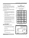
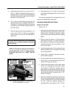
4. Pack 4.8 oz. of grease in the outer circumference
of the inner bearing cap as shown by the shaded
area in the bearing cap.
5. Install the inner bearing cap on the sleeve.
6. Heat and install the flinger tight against the
sleeve.
7. Heat and install the inner race of the roller bear-
ing tight against the flinger.
8. Install the outer race of the bearing in the
framehead.
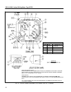
9. Fill the roller bearing completely with 29.0 oz. of
grease.
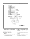
10. Install the gasket onto the inner bearing cap.
11. Install guide pins into the inner bearing cap to
guide the framehead into position.
12. Assemble the framehead/bearing assembly
onto the shaft, over the guide pins until seated
against the bearing cap. Remove the guide pins.
NOTE: Orient the inner bearing cap on UP, AUP,
US and AUT models to facilitate grease tube as-
sembly.
13. Assemble the grease tubes to the inner bearing
cap:
a. On UP1 and AUP1 models, there are two
grease tubes, assembled to the inner bearing
cap and protrude through a hole in the frame.
b. On UP2 and AUP2 models, there is one
grease tube, assembled to the inner bearing
cap and protrudes through a hole in the
frame.
c. On all other models, there is one grease tube
assembled to the inner bearing cap and pro-
trudes through a hole in the framehead.
14. Pack 4.8 oz. of grease in the outer circumference
of the outer bearing cap and install the bearing
cap to the framehead. Secure the assembly with
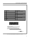
bolts and lockwashers. Torque to the appropriate
value in Table 3, Page 37.
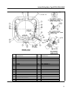
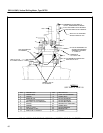
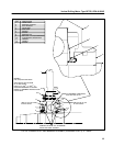
Commutator–End Bearing
(All Models Except US2, UP6, AUT2 and AUP5)
Refer to Fig. 38.
1. Clean and inspect the bearing and the shaft
bearing fit. Remove nicks and burrs.
2. If sleeve (16) was removed, heat it to 110_ C
(230_ F) and shrink it tight onto the shaft against
the shoulder.
3. Pack 5.25 oz. grease into the outer circumfer-
ence of the cavity of bearing housing (8).
4. Heat bearing housing (8) in an oven to 100_ C
(212_ F). While hot, assemble ball bearing (3)
into the housing firmly against the shoulder at the
bottom of the bearing fit.
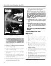
5. Fill all voids in the ball bearing completely with
approximately 20.8 oz. of grease, Fig. 38. Smear
0.5 oz. of grease on the bearing housing and the
bearing cap seals.
6. Heat the bearing and housing assembly in an
oven to 100_ C (212_ F). While hot, assemble it
onto the shaft, with the inner race tight against
sleeve (16).