


GEK–91584D, Vertical Drilling Motor, Type GE752
68
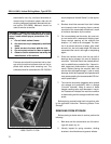
ing caps. Thermometers should contact the
bearing caps for best results.
2. Seat the brushes and run for ten minutes at 900
rpm.
Frame temperature should not exceed 25 C rise.
3. With machine running up to speed, measure vi-
bration. Vibration should not exceed 0.002 on
commutator end. If vibration exceeds this
amount, rebalance the armature.
4. Check the commutator for roughness and make
sure the brushes are riding properly.
5. Use a listening rod to check for noisy bearings.
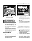
6. Stop the machine and mount an indicator on the
frame. While turning the armature by hand, mea-
sure commutator runout. It should not exceed
0.001 in.
7. Measure field impedance. With 60 Hz a–c and 24
amperes through each field, measure the volt-
age drop across total exciting and commutating
fields. See the DATA section for voltage limits.
8. Apply a high–potential test to the windings of the
assembled machine, as specified in the DATA
section.
WARNING: Electric shock can cause serious
or fatal injury. Proper precautions should be
taken and observed by personnel performing
testing to avoid such injury.
TESTING SHUNT MACHINES
(Models 5GE752UP and US)
After the motor has been reconditioned and reas-
sembled for service, make the following tests to be sure
it will operate satisfactorily.
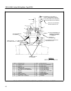
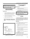
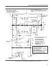
Connect the motor to a d–c welding generator. Refer
to connection diagrams (Figs. 21 and 23) for connec-
*Product of Johns Manville Co.
tions. Run the machine by separately exciting the shunt
field from a 125 vdc source. From another source of
power, apply voltage to the armature circuit until the de-
sired speed is obtained.
Motor Operation
Ventilated (2300 cfm at 7.6 in. H
2
O
at Commutator Chamber)
Hold separate field excitation at 50.5 amperes. Vary
the armature voltage to obtain the required rpm. At ap-
proximately 700 terminal volts (no load), the speed will
be 900 rpm.
Unventilated
Hold the separate field excitation at 10 to 15 am-
peres. Vary the armature voltage to obtain the required
rpm. At approximately 338 terminal volts (no load), the
speed will be 900 rpm.
1. Run the motor for five minutes at 450 rpm. In-
crease the speed to 900 rpm and run for two
hours. Bearing temperatures should not exceed
70_ C (158_ F). Run until the bearing tempera-
ture remains constant for 30 minutes. Increase
the speed to 1300 rpm and hold it while perform-
ing Steps 2, 3 and 4. Then shut down the motor.
Do not exceed 1300 rpm.
2. Measure vibration when running the motor up to
speed. Vibration should not exceed 0.004 in. If
excessive, rebalance the armature.
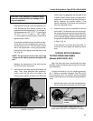
3. Check the commutator for roughness. Be sure
brushes are riding properly.
4. Listen for noisy bearings with a listening rod.
5. Stop the motor and mount an indicator on the
frame. Turn the armature by hand and measure
commutator runout. Runout should not exceed
0.001 in.
6. Measure the insulation resistance of the wind-
ings with a megohmmeter. If the resistance mea-
sures not less than one megohm, apply an a–c
high–potential test to ground for one minute as
outlined in the DATA section.