


GEK–91584D, Vertical Drilling Motor, Type GE752
38
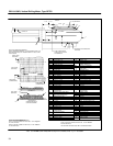
NOTE: Before rewinding the armature, first
check the shaft pinion and bearing fits to deter-
mine whether or not shaft replacement is re-
quired. See Table 2 to determine the correct
shaft drawings.
The armature can be rewound using a GE Co. Sup-
ply Kit, Part 41D730545G8, and the information
supplied in the kit.
NOTE: After the armature is rewound, the arma-
ture coil leads must be TIG welded to the com-
mutator risers, the armature must be Vacuum
Pressure Impregnated, and the commutator
must be cleaned and polished.
Commutator Tightening
If the commutator requires tightening, commutator
assembly pressure can be restored at overhaul by per-
forming a commutator tightening procedure; however, it
is necessary that spin–seasoning and resurfacing oper-
ations be performed after the commutator is tightened.
Before proceeding to tighten a loose commutator, it
must first be determined whether or not the brush–sur-
face diameter of the commutator will be larger than the
minimum permissible diameter after the commutator is
resurfaced.
If the brush–surface diameter is calculated to be
smaller (after resurfacing) than the minimum
permissible diameter, listed in the DATA section, the
commutator must be replaced.
After a long period of service, the mica insulation
may relax, due to temperature cycling, and relieve com-
mutator assembly pressure. This could result in a loose
commutator (with raised bars), or an out–of–round com-
mutator.
The assembly pressure can be restored by tighten-
ing the commutator bolts. This must be done before un-
dertaking any resurfacing operation on the commutator.
Procedure
1. Chip the weld from the commutator bolt heads to
free bolts from the cap.
2. Torque the commutator bolts by one of the fol-
lowing methods.
Hydraulic Press (Preferred Method)
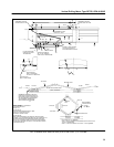
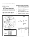
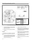
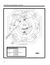
1. Clean the front face of the cap and the segments,
Fig. 25. Remove ONE bolt at a time, and lubri-
cate the bolt threads and under the bolt head.
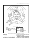
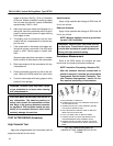
See Lubrication of Bolts section. Follow the se-
quence shown on Fig. 27 for bolt removal. Reas-
semble bolt and tighten to the initial breakaway
torque value.
2. Using a depth micrometer, measure the distance
(X in Fig. 25) between the face of the cap and the
segments at four points, 90 degrees apart. The
face of the cap and the segments should be par-
allel within 0.020 in. If necessary, tighten the ap-
propriate cap bolts to obtain this parallel relation-
ship between the face of cap and the segments.
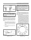
3. Place the armature in a vertical press. Position
ball and socket tool (Part 41C685080G1) and
crow–foot pressing fixture (Part 41C685430G1)
on the commutator, and apply 70 tons pressure
at the diameter shown on Fig. 26.
4. Tighten the commutator bolts to 145 lb.–ft.
torque in a crisscross sequence, Fig. 27. Tighten
the bolts twice in this sequence, then tighten
bolts once–around at 145 lb.–ft. torque.
NOTE: The specified torque values have no sig-
nificance unless the bolts are lubricated.
5. Check the dimension between cap face and seg-
ments at four locations, 90 degrees apart, to as-
sure surfaces are still parallel within 0.020 in.
Torque Wrench (Acceptable Method)
In the absence of a suitable press, bolts may be tight-
ened with a torque wrench adjusted to apply the indi-
cated torque to each bolt.
1. Clean the front face of the cap and the segments.
Using a depth micrometer, measure the distance
(X in Fig. 25) between the face of the cap and the
segments at four points, 90 degrees apart. The
face of the cap and the segments should be par-
allel within 0.020 in.