


Vertical Drilling Motor, Type GE752, GEK–91584D
21
3
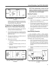
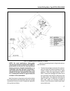
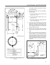
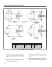
FIG. 13. COMMUTATOR–END BEARING PILOT.
E–18150.
heavy paper around the commutator for protec-
tion during handling.
4. Remove grease tubes from the commutator–
end bearing cap:
a. On UP1 and AUP1 models, there are two
grease tubes (19, 20).
b. On UP2 and AUP2 models, there is one
grease tube (19).
c. On all other models, only a pipe plug is pro-
vided in the bearing cap.
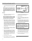
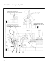
5. Install puller (Part 6751547G4) and pull sleeve
(42) from the shaft at the commutator end. The
sleeve has four tapped holes for applying the
puller. Apply heat to the sleeve with a torch while
pulling to facilitate removal.
6. Remove bolts and washers (52) and remove
bearing cap (4) and gasket (57) from the frame
head.
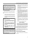
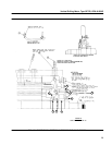
7. Make sure the armature locking arrangement is
securely installed. Turn the machine on end on a
stand (commutator–end down) and level it so the
armature can be lifted vertically out of the frame
without damaging the bearings, commutator or
brushholders. Remove the armature locking ar-
rangement.
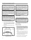
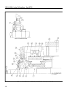
FIG. 14. ARMATURE LIFTING BAIL. E–23932.