


GEK–91584D, Vertical Drilling Motor, Type GE752
44
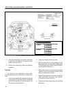
edges of the bars. See Fig. 12 for an illustration
of the tool. Another method of removing copper
fins is to rake the slots with a piece of fiberboard
approximately 0.045 in. thick.
2. After slots have been raked with fiberboard or a
raking tool, sand the commutator with fine sand-
paper to remove small pieces of copper sticking
from edges of slots.
3. Thoroughly clean the armature core and com-
mutator with dry, compressed air to remove cop-
per and dust.
1. If the commutator is discolored or smudged, pol-
ishing with canvas, crocus cloth, fine (4/0) sand-
paper or 400A Triemite paper is usually suffi-
cient.
Abrasive paper should be mounted on a wooden
block curved to fit the surface of the commutator.
2. Blow loose material off the commutator with dry,
compressed air.
3. Check commutator concentricity with a dial indi-
cator. Refer to the DATA section for runout limits.
4. Cover the commutator with heavy paper or felt to
protect it from damage.
WARNING: Personal injury may result if prop-
er eye protection is not worn when cleaning
with compressed air.
CAUTION: Never use an emery cloth on this or
any commutator. The abrasive particles on
emery cloth scratch the commutator surface
and lodge in the grooves between commuta-
tor segments. This condition creates the pos-
sibility of an eventual flashover which could
seriously damage the machine.
TEST AFTER REPAIR (Armature)
High Potential Test
Apply test voltage between the commutator (with all
segments shorted) and the shaft.
Used Armature
Apply a high–potential test voltage of 2000 volts, 60
Hz for one minute.
Rewound Armature
Apply a high–potential test voltage of 3500 volts, 60
Hz for one minute.
NOTE: Measure leakage current to ground dur-
ing test 3–85.0 milliamps.
WARNING: Electric shock can cause serious
or fatal injury. To avoid such injury, personnel
should take and observe proper precautions
during the high–potential testing.
Resistance Measurement
Refer to the DATA section for armature the resis-
tance value and measure armature resistance.
NOTE: Insulation Processing (Armature VPI)
After the armature has been cleaned and re-
paired or rewound, it must be vacuum pressure
impregnated. See the Varnish Treatment, “Vac-
uum Pressure Impregnation” section for fur-
ther required processing of the armature.
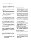
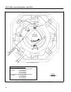
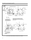
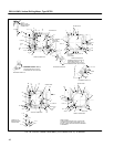
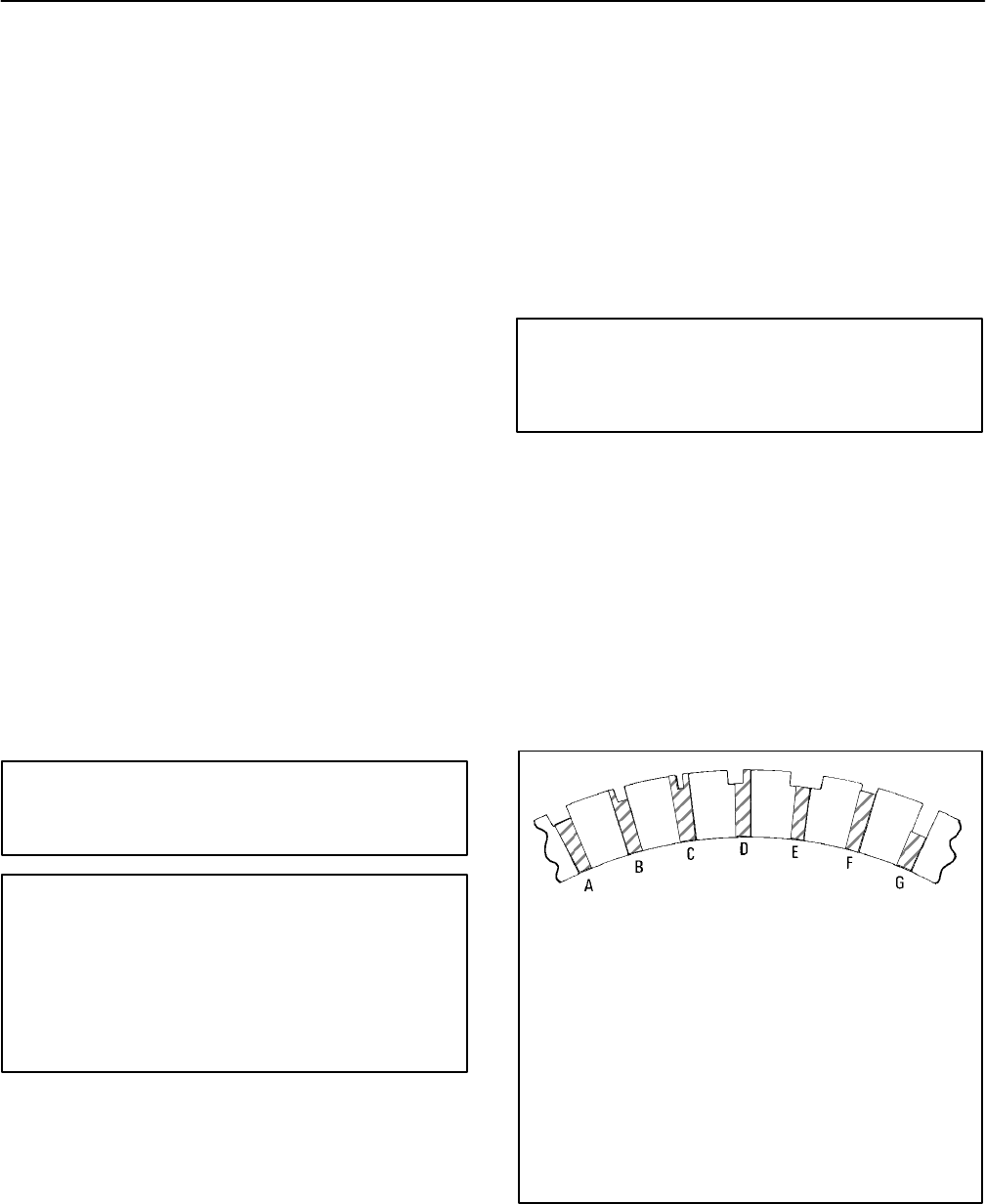
A. MICA PROPERLY UNDERCUT.
B. UNDERCUTTING TOOL TOO NARROW, LEAVING FIN
AT ONE SIDE OF SLOT.
C.UNDERCUTTING TOOL VERY NARROW, LEAVING
FINS AT BOTH SIDES OF SLOT.
D.SLOT IMPROPERLY INDEXED, PART OF BAR CUT
AWAY AND FIN OF MICA LEFT.
E. TOOL TOO WIDE, PART OF BAR CUT AWAY.
F. UNDERCUTTING TOO SHALLOW, SERVICE LIFE
SHORTENS BEFORE NEXT UNDERCUTTING.
G.UNDERCUTTING TOO DEEP, POCKET COLLECTS
CARBON AND COPPER DUST, SHORT CIRCUITING
BARS.
FIG. 28. COMMON MISTAKES IN
UNDERCUTTING COMMUTATOR SLOTS.
E–5024A.