Vertical Drilling Motor, Type GE752, GEK–91584D
37
ARMATURE
Creepage Band Replacement
Because of its superior adhesion qualities, the Teflon
creepage band on the outer end of the commutator
should be applied using the “hot bond” process. A copy
of this process is included in each Teflon Band Kit, Part
No. 76518, which can be ordered from the following ad-
dress:
General Electric Company
Insulating Materials Product Section
One Campbell Road
Schenectady, NY 12345
Attn: Customer Service
NOTE: The Teflon band is not included in the
kit, but can be ordered through normal Renewal
Parts channels.
Inspect the Band
1. There should be no gaps at the joint or between
the edge of the Teflon band and the copper bars.
2. The band surface must be smooth, free of var-
nish and bonded to the underlay material. There
must not be any bubbles under the Teflon or
buckling of the band.
3. The surface must be free of damage including
scratches and cuts.
Rewinding Armature
The armature must be rewound if any coils are
shorted or grounded.
Riser Width
During the rewinding procedure, the TIG welds on
the commutator risers are machined to break the arma-
ture coil connections. Machining reduces the width of
the risers 1/32 to 1/16 in. each time, which in turn de-
creases the current–carrying capacity of the risers.
If the calculated width of the risers (after machining)
will be less than the Minimum Permissible Riser Width
listed in the DATA section, a new commutator must be
installed before new armature coils are assembled.
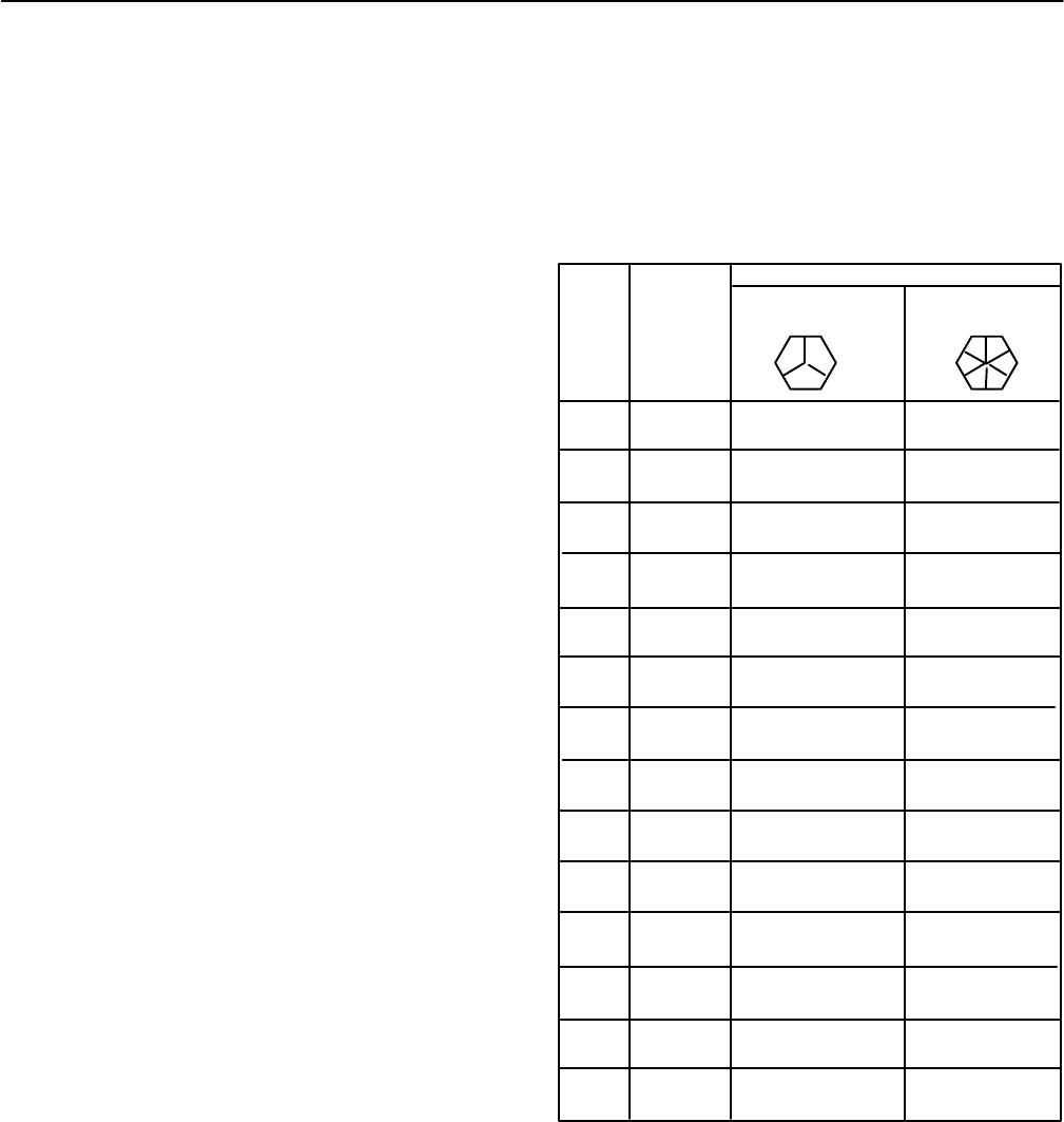
TABLE 3
STANDARD BOLT TORQUE VALUES
USE THE TORQUE VALUES IN THIS TABLE AS A GUIDE TO IN-
SURE SATISFACTORY TIGHTENING OF BOLTS AND NUTS
WHERE A SPECIFIC VALUE IS NOT GIVEN IN THE INSTRUC-
TIONS.
*INCLUDES SOCKET HEAD SCREWS.
1/4 20 5–8 10–12
28 5–8 10–12
5/16 18 12–15 18–21
24 12–15 20–23
3/8 16 20–25 30–36
24 25–28 34–40
7/16 14 35–40 50–56
20 40–45 60–65
1/2 13 55–60 80–90
20 60–70 95–105
9/16 12 75–80 110–123
18 90–100 130–145
5/8 11 105–115 152–169
18 125–140 185–205
3/4 10 185–205 285–315
16 220–245 340–370
7/8 9 300–330 440–490
14 340–380 510–565
1 8 440–490 685–735
12 530–570 790–8665
1–1/8 7 620–690 935–1040
12 750–830 1115–1240
1–1/4 7 890–990 1250–1360
12 1040–1160 1600–1750
1–3/8 6 1160–1290 1745–1940
12 1420–1580 2125–2360
1–1/2 6 1570–1740 2300–2600
12 1800–2000 2600–3020
THREADS
PER
INCH
TORQUE VALUES (LB./FT.)
MEDIUM CARBON
(SAE GRADE 5)
ALLOY STEEL
(SAE GRADE 8)*
BOLT
DIAM.
E–38274
(For Lubricated Bolts)
Diameter
Refer to the DATA section for the Minimum Permissi-
ble Commutator Diameter dimension. If the commutator
brush–surface diameter will be less than the minimum
permissible diameter after resurfacing operations are
performed, replace the commutator before the new ar-
mature coils are assembled.


