


GEK–91584D, Vertical Drilling Motor, Type GE752
30
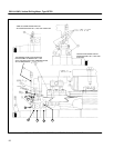
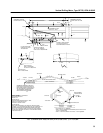
8. Screw a lifting bail, Fig. 14, on the drive end of the
shaft.
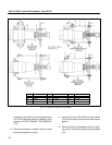
9. Remove drive–end framehead bolts (30) and in-
sert three jack screws in the threaded holes pro-
vided in the framehead.
10. Line up the hoist cable with the centerline of the
armature before engaging the hook in the lifting
bail on the end of the shaft. Engage the hook and
lift slightly. With sufficient strain on the hoist
cable to take the weight of the armature off the
framehead, jack the drive–end framehead loose,
and lift the complete armature assembly out of
the frame. DO NOT DAMAGE THE COMMUTA-
TOR.
CAUTION: Special precautions should be taken to
avoid damage to the armature end–windings,
bearings or bearing fits, and the commutator
when lifting the armature in the vertical position
or turning the armature to a horizontal position.
11. Place the armature horizontally in an armature
saddle for bearing disassembly.
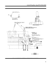
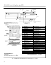
12. At the drive end, remove the lubricating tube as-
sembly (9, 33, 32 and 28) from the framehead.
13. Using puller tool (Part 6751547G4), pull the out-
er sleeve (37) from the drive end of the shaft. The
sleeve has tapped holes for applying the puller.
Heat may be applied.
14. Remove bolts (34), and then remove outer bear-
ing cap (36) and gasket (35).
15. Slide framehead (29) off the shaft together with
the outer race and rollers of bearing (38). The in-
ner race will remain on the shaft.
16. Pull the inner bearing race off the shaft with puller
(Part 6751547G5).
17. Remove flinger (39) and inner bearing cap (40)
with puller (Part 6751547G6) by inserting the
four puller bolts into the tapped holes in inner
bearing cap (40).
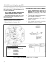
18. Press the outer bearing race and rollers from the
framehead with an arbor press.
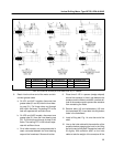
NOTE: Before pressing the drive–end outer
bearing race out of the framehead, observe and
record the number on the face of the race which
is opposite the arrow on the framehead. After
removal, mark the date (with electric pencil) un-
der this number to indicate that this position
has been used. Reassemble the bearing with
another number opposite the arrow. If the bear-
ing has not been previously marked, etch Nos.
1, 2, 3 and 4 (spaced 90 degrees apart) on the
face of race with an electric pencil. Locate No. 1
opposite the arrow on the framehead and mark
it with the date.
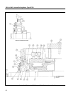
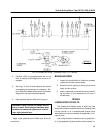
19. Install puller tool (Part 6751547G10) and pull
spacer (5) from the commutator end of the shaft.
20. Install puller tool (Part 6751547G6) and pull
bearing (4) and bearing housing (3) from the
commutator end of the shaft.
21. Press the bearing from the framehead with an
arbor press.
22. If applied, remove the nilos ring (4), Fig. 39, from
the bearing and discard.
23. If applied, remove the seal ring (5) Fig. 39, from
the sleeve and discard.
24. Install puller tool (Part 6751547G11) and pull
sleeve (2) from the commutator end of the shaft.
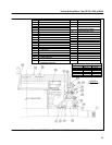
25. If necessary to remove the commutator
framehead (14), turn the frame commutator end
up and remove bolts and lockwashers (13). Use
bolts in the framehead jack–out holes to break
the fit and remove.
CLEANING
The two recommended methods for cleaning are
steam cleaning and vapor degreasing.
CAUTION: Do not use caustic soda solution
on the armature or coiled frame.
Steam Cleaning
(Recommended for both insulated and metal parts)
1. Use steam in combination with a commercial
non–caustic cleaner.