


GEK–91584D, Vertical Drilling Motor, Type GE752
54
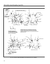
NOTE: If a gas torch is used, coil insulation
must be protected from heat by a non–flam-
mable heat absorbent.
1. Pack absorbent around the insulation near
the connection and over adjacent coils.
2. Make sure all exposed insulation is covered
with a thick layer of absorbent, then heat and
separate the coil connections.
2. Heat the coiled frame in an oven at 150_ C (302_
F) for four hours to soften the varnish so pole
bolts can be removed.
Remove the pole bolts and the coil–pole assem-
bly from the magnet frame.
3. Mark any shims for reassembly with the corre-
sponding pole when the coil(s) is installed in the
frame.
Coil Installation
Procedure for New Coil–Pole Assembly
NOTE: Install any exciting coils and braze their
connections before installing commutating
coils.
1. Before installing any coil and pole, clean the pole
contact surface on the frame and the pole piece
mounting surface.
2. Install the new pole and coil in the frame with any
shims that were on the damaged coil. Use new
washers under bolt heads. Lubricate the bolt
heads, threads and washers and draw the pole
bolts moderately tight.
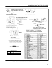
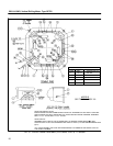
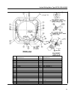
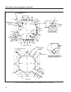
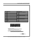
3. Refer to Table 2, Page 20, to determine the cor-
rect coiled frame assembly drawings. All coil
connections must be brazed with silver solder,
GE–B20A6. Use two pieces of solder (0.010 x 1
in. x 1 in.) between terminal surfaces and braze
terminals as follows:
Brazing Coil Terminals
Braze the coil terminals by one of the following meth-
ods:
Machine Brazing
1. The recommended brazing current is 10,800
amperes at 1.6 volts. With silver–solder brazing
strips inserted between connections, clamp the
brazing tongs on the connection and braze the
joint. If necessary, add additional solder to fill the
joint and form a level surface.
2. Braze all exciting–coil connections before install-
ing the commutating coils.
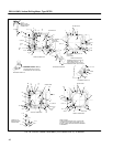
Gas Torch Brazing
1. Pack the coil insulation with non–flammable heat
absorbent material; e.g., interwoven glass cloth.
2. Insert the brazing strips and use a C–clamp or vi-
se–grip pliers to clamp the connection surfaces
tightly together.
3. Use a torch tip with a 0.1 in. orifice and adjust the
torch to obtain a slightly reduced flame. As the
brazing strips melt, add more solder to fill the
joint and form a level surface.
4. Remove heat absorbent packing from insulation.
Use dry, compressed air and blow out the inside
of the frame.
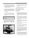
WARNING: Personal injury may result if prop-
er eye protection is not worn when cleaning
with compressed air.
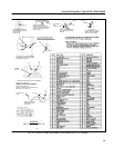
5. Torque the pole bolts to the values listed in Table
3, Page 37, Standard Bolt Torque Values.
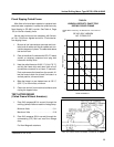
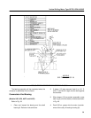
6. Check the polarity of the field poles:
Energize the field circuit with a battery and check
pole polarity with a compass, Fig. 33.
7. Insulate the connections with silicone putty and
wrap connections with Mylar film (30). Apply
glass tape and extend each taping 1/2 in. beyond
the bare area of the connection. Brush the con-
nections with air–drying alkyd varnish GE–8001.
8. Install and connect any cables previously re-
moved.
NOTE: Do not flood–dip the coiled frame before
the cables are installed and the connections are
insulated.