


Vertical Drilling Motor, Type GE752, GEK–91584D
39
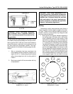
If necessary, tighten the appropriate cap bolts to
obtain this parallel relationship between the face
of the cap and the segments.
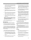
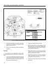
2. Remove ONE bolt. Clean and lubricate the bolt
threads under the bolt head. Reassemble bolt,
and torque to 97 lb.–ft.
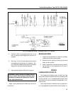
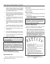
3. Repeat Step 2 for remaining bolts, following the
crisscross tightening sequence shown on Fig.
27.
4. Repeat the tightening sequence increasing the
torque by 10% each time until a FINAL value of
145 lb.–ft. torque for all bolts is obtained.
5. Check the dimension between face of cap and
segments to assure these surfaces are parallel
within 0.020 in.
NOTE: Do not tack–weld the bolts to the com-
mutator cap before spin seasoning or resurfac-
ing operations are performed.
Refer to following sections for instructions to spin
season and resurface the commutator.
Spin Seasoning
(Commutator Assembled On Armature)
A commutator seasoning cycle is required after com-
mutator tightening operations have been performed.
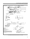
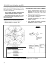
Prior to spin–seasoning, dynamically balance the ar-
mature to within 12 grams on the commutator end and
10 grams on the drive end. Refer to longitudinal section
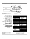
for balance weight locations (see Table 2 to determine
the correct drawing).
To spin season the commutator, place the armature
in a spin–seasoning stand and proceed as follows:
1. Heat the commutator to 155–165_ C (312–330_
F) in 60 minutes at 2940 rpm. Spin at 155–165_
C (312–330_ F) for 60 minutes at 2940 rpm. Cool
to 50_ C (122_ F) maximum in 30 minutes at
2940 rpm.
2. Allow the commutator to cool, and grind cold.
See “Commutator Resurfacing” section.
3. Heat the commutator to 155–165_ C (312–330_
F) in 60 minutes at 2940 rpm. Spin at 155–165_
C (312–330_ F) for 30 minutes at 2940 rpm. Cool
to 50_ C (112_ F) maximum in 30 minutes at
2940 rpm. Repeat for a total of 2 cycles.
4. Heat the commutator to 140–150_ C (284–302_
F) in 60 minutes at 2940 rpm, and check commu-
tator smoothness at 2940 rpm.
5. Allow the commutator to cool, and grind cold.
See the “Commutator Resurfacing” section.
Check commutator runout per the information in
the DATA section. If the commutator is rough or
has high bars, repeat the pressing, tightening,
spin–seasoning and resurfacing procedures un-
til the runout is within the limits specified in the
DATA section.
6. Tack–weld the bolts to the commutator cap with
bronze welding rod, GE–B50E37.
7. Refer to the “Test After Repair (Armature)” sec-
tion for the test voltage, and perform a High–Po-
tential test on the armature windings.
Commutator Resurfacing
Prior to turning or grinding the commutator, be cer-
tain there is sufficient stock so the commutator will not
be turned or ground below the minimum permissible di-
ameter.
Refer to the DATA section for the minimum permissi-
ble commutator diameter dimension.
If the brush surface diameter will be less than the
minimum permissible diameter after the resurfacing op-
erations are performed, the commutator must be re-
placed.
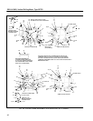
Grinding
1. Prior to grinding, true the shaft centers with re-
spect to the bearing fits by scraping.
2. Place the armature in a lathe equipped with a
grinding attachment or in a grinding machine.
Check the concentricity of the bearing fits. The
TIR should not exceed 0.001 in.
3. Cover the armature windings to prevent entry of
grinding dust and chips.