


Vertical Drilling Motor, Type GE752, GEK–91584D
67
CAUTION: Zero settings of advance gauge
must not be disturbed until all readings on the
hub are completed.
Heat the hub in an oven until it has reached a uni-
form temperature (the desired number of de-
grees above shaft temperature). For example, if
shaft temperature is 25_ C (77_ F), heat hub to
25_ C (77_ F) +171_ C (339_ F) = 196_ C (385_
F). This procedure should provide an advance of
approximately 0.085 in.
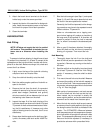
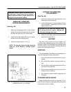
An accurate method must be provided for mea-
suring hub and shaft temperatures quickly be-
fore mounting the hub. This can best be done
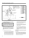
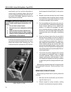
with a hand pyrometer. In using the pyrometer,
place points of the gauge inside the bore of the
hub, Fig. 42.
NOTE: The part must be left in the oven long
enough for the heat to penetrate throughout the
part.
Measure the temperature of the shaft and the
hub with the same instrument.
5. Insure that the hub bore and the shaft taper are
clean. Then, using adequate hand protection,
quickly mount the hot hub on the shaft in the
same angular position as when cold. When the
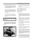
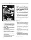
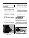
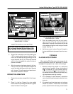
FIG. 41. METHOD OF USING ADVANCE
GAUGE. E–5975A.
hub is nearly in engagement with the taper fit (not
in actual contact), snap it forcibly into place with a
quick push. It is important that the hot hub be in-
stantly snapped into position before it has
cooled; otherwise, it will freeze to the shaft and
cannot be adjusted further.
6. Check the hot or shrunk–on position of the hub
on the shaft. The advance from cold to hot posi-
tion along the axis of the shaft must be held with-
in the limits indicated. Check the actual advance
with an indicator gauge, located in the same rela-
tive position as used to measure the cold position
in Step 3, Fig. 41.
If the advance is not within specified limits, re-
move the hub and repeat the assembly proce-
dure.
TESTING AFTER OVERHAUL
TESTING SERIES MACHINES
(Models 5GE752AUP, AUT)
After the motor has been reconditioned and reas-
sembled, make the following tests to assure it will oper-
ate satisfactorily.
Connect the motor to a d–c arc–welding generator,
Fig. 7. Refer to connection diagrams, Figs. 22 and 24,
for connections. Run the machine series–connected
without load at 900 rpm and measure bearing tempera-
tures.
1. Use Duxseal* putty to hold the thermometers on
the drive end and commutator–end outer bear-
PLACE PYROMETER
POINTS IN BORE
OF HUB
FIG. 42. MEASURING TEMPERATURE OF
COUPLING HUB WITH PYROMETER. E–5976.