Vertical Drilling Motor, Type GE752, GEK–91584D
69
WARNING: Electric shock can cause serious
or fatal injury. To avoid such injury, personnel
should take and observe proper precautions
during the high–potential testing.
REMOVING ARMATURE
LOCKING ARRANGEMENT
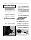
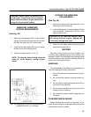
(See Fig. 43)
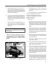
1. Remove the two shipping bolts (1) from the bear-
ing cap. These bolts are longer and can be identi-
fied from the factory by their yellow heads.
2. Install the two regular bolts which are in a bag at-
tached to one of the shipping bolts.
3. Torque the regular bolts to 115 lb.–ft.
NOTE: The shipping bolts and bag should be
saved for future armature locking require-
ments.
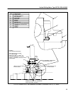
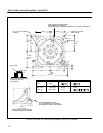
FIG. 43. ARMATURE LOCKING ARRANGEMENT
(41B535748 CHG. 0). E–28735A.
LOCKING THE ARMATURE
FOR SHIPMENT
(See Fig. 43)
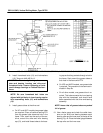
1. Remove two diametrically opposite bolts in the
commutator end bearing cap.
2. Install shipping bolts (1) (painted yellow) with jam
nuts (2) applied. Torque bolts to 30 lb.–ft. and
tighten the jam nuts.
CAUTION: Do not rotate the armature when
the locking bolts are in place. Bearing and
commutator damage may result.
3. Attach the two regular bolts and bag–tag (5) to
one of the locking bolts (1).
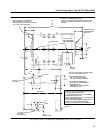
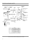
SHIPPING
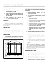
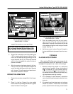
Whenever drilling motors are to be shipped, they
must be properly skidded and secured to prevent any
damage in transit. The photographs and drawings which
follow illustrate a proven method of skidding these ma-
chines for handing and shipment.
HANDLING
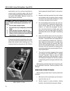
To avoid damage to the machine during handling, re-
view the following cautionary statements:
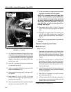
1. Do not lift motors by the shaft extension of the ar-
mature.
2. Do not allow the armature to bump another ob-
ject.
3. Do not tighten coupling assembly bolts with an
air wrench or by pounding.
4. Do not remove armature end–play by any other
means than axial blocking.
5. Do not load the armature radially (strap down) for
shipment.
CLEANING AND SLUSHING
Before skidding the machine for shipment, all ex-
posed finished surfaces not already painted should be
cleaned and slushed as follows:


