


120 TRIGGER 70903 !Trigger the switchbox to advance
the channel list
130 NEXT I !Increment count
140 END
Scanning Voltmeter When the multiplexer(s) is combined with a multimeter to form a single
instrument, they become a virtual instrument, a scanning voltmeter. The
multiplexer(s) and the multimeter have the same secondary address. The
multimeter automatically configures the multiplexer, so the
SCAN:MODE,
SCAN:PORT and TRIG:SOUR commands are not required. Channel
advance is from the digital bus handshake lines, so the count loop is not
required. The
ARM:COUN command does not apply to downloaded scan
lists, so you cannot specify the number of cycles through the scan list. You
can, however, specify
INIT:CONT ON for continuous scanning through the
scan list.
10 DIM Rdgs(1:16) !Dimension an array for 16
readings
20 OUTPUT 70903;"*RST" !Reset instrument
30 OUTPUT 70903;"MEAS:VOLT:DC? (@100:115)"
!Configure instrument
40 ENTER 70903;Rdgs(*) !Enter readings into array
50 PRINT Rdgs(*) !Print results
60 END
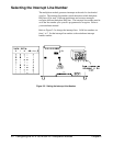
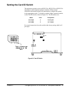
Digital Bus and Triggering
The HP E1351A/E1353A can be triggered for channel advance from the
VXIbus backplane or through the digital bus handshake cable on the front
of the component assembly. Backplane triggering can come from HP-IB
computer commands over the HP-IB Bus or from the HP E1300/1301
Mainframe "Event In" port. Digital bus triggering uses two handshake
lines; channel advance and channel closed. Channel advance (input to
multiplexer) triggers an advance, and channel closed (output from
multiplexer) signifies advance completed.
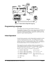
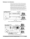
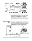
The HP E1326B Multimeter has a digital bus port on the face plate, and
connects to the multiplexer with the digital bus cable (see Figures 2-10 and
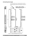
2-11). To connect other multimeters for digital bus triggering, you must
prepare a custom cable. Use a connector like the one on the digital bus
cable (HP part number E1300-61611). Connect the measurement complete
port from the multimeter to the channel advance pin, and the external trigger
to the channel closed pin. Connect the grounds for both signals to the
digital bus ground (second pin from right). You can use this cable to
connect an external multimeter to a switchbox, and then use
TRlG:SOUR
DBUS
(digital bus triggering). You can also order a custom cable with
BNC to digital bus connectors, HP part number E1411-80001. See Figure
2-11 for more information on multiplexer-to-multiplexer and
multiplexer-to-multimeter connections.
Chapter 1 Getting Started with the HP E1351A/53A 15