


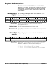
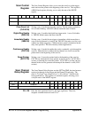

The [ROUTe:]SCAN:MODE VOLT | RES | FRES is set with C1 and C0 in
the Scan Channel or Direct Control Register. Note that to obtain the
Thermistor reference temperature for Thermocouple measurements, you
must set the configuration bits for Thermistor. After you have obtained the
reference temperature, set the bits for Volts.
C1 C0
0 0 Volts
0 1 2-wire ohms
1 1 4-wire ohms
1 0 Thermistor
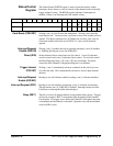
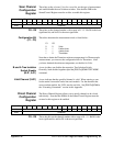
[ROUTe:]SCAN:PORT NONE | ABUS
is set with A_D* and B_D* on the
Scan Channel Configuration or Direct Control Registers. Set both bits to
one for
ABUS and to zero for NONE.
[ROUTe:]SETTling[:TIME] is set with the D3 to D0 bits in the Scan
Channel Delay Register. The bits form a number
n
(
n
is between 0 and 16),
and the delay is 2
n
µsec.
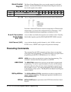
SYSTem SYSTem:CDEScription? is a READ on the Manufacturer ID Register.
SYSTem:CTYPe? is a READ on the Device Type Register.
SYSTem:CPON can be achieved by setting the DIR bit true in the
Status/Control Register and setting VLD* false. This opens all channels
without a card reset.
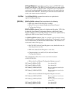
TRIGger TRIGger[:IMMediate] is equivalent to writing a one to TRG INT in the
Status Control Register. The register returns to zero after pulsing the
channel.
TRIGger:SOURce IMMediate and TRIGger:SOURce DBUS are executed
with the IMM EN and DBS EN bits in the Scan Control Register.
TRIGger:SOURce BUS and TRIGger:SOURce EXTernal are not
implemented at the register level. These commands both write to the TRG
INT bit when they are active and a trigger occurs.
TRIGger:SOURce HOLD is not implemented at the register level. It is in
the normal state when all trigger sources are disabled.
92 HP E1351A/53A Register-Based Programming Appendix B