


Example: Scanning
Using "Trig Out" and
"Event In" Ports
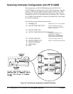
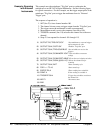
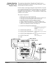
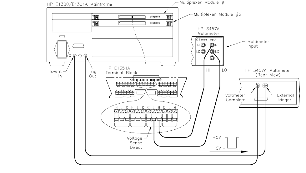
This example uses the mainframe "Trig Out" and "Event In" ports to
synchronize the multiplexers to an HP 3457A Digital Multimeter. See the
following figure for typical connections.
For this example, use the trigger output pulse of the mainframe’s "Trig Out"
port to trigger the multimeter from its "External Trigger" port. Note that the
pulse output from the multimeter’s "Voltmeter Complete" port triggers the
switchbox to advance the channel list. Use the multimeter’s reading storage
capability to store readings.
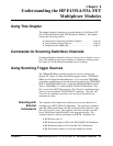
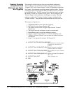
The sequence of operation is:
1.
INIT (line 50) closes channel number 100.
2. The channel closure causes a trigger output from the "Trig Out" port.
3. The trigger causes the multimeter to make a measurement.
4. Measurement result is stored into multimeter memory.
5. Trigger is output from multimeter’s "Voltmeter Complete" port.
6. Trigger to "Event In" port advances the channel list to the next channel.
7. Steps 2-6 are repeated for channels 101 through 115.
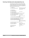
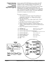
10 OUTPUT 722;"TRIG EXT:DCV:MEM FIFO"
!Sets multimeter to external trigger
to measure dc volts and store
readings
20 OUTPUT 70914;"OUTP ON" !Enables "Trig Out" port
30 OUTPUT 70914;"TRIG:SOUR EXT" !Sets switchbox to receive external
triggers
40 OUTPUT 70914;"SCAN (@100:115)"!Selects the channel list (channels
100 to 115)
50 OUTPUT 70914;"INIT" !Starts scanning cycle
60 END
Chapter 4 Understanding the HP E1351A/53A FET Multiplexer Modules 49