


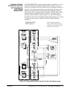
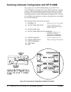
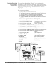
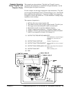
Scanning Voltmeter Configuration with HP E1326B
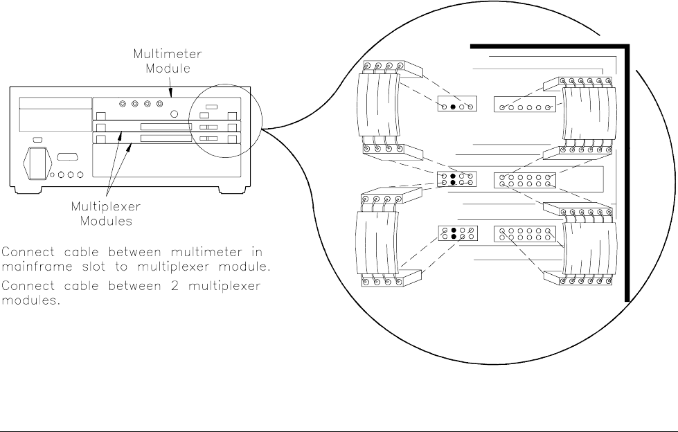
This example shows an HP E1326B Multimeter and an HP E1351A/
E1353A Multiplexer combined into a single VXIbus instrument, a scanning
voltmeter. The secondary address for the scanning voltmeter is 03. Both
the analog bus connector and the digital bus connector are used. Once the
scanning starts, there is no intervention from the mainframe CPU. The scan
list is in RAM on the multiplexer, and the two handshake lines on the digital
bus control the triggering.
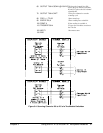
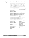
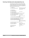
The following program illustrates the procedures:
10 DIM Rdgs(1:16) !Dimension array to store readings
20 OUTPUT 70903;"*RST;*OPC?" !Clear the multimeter; OPC?
ensures reset is completed before
program continues
30 OUTPUT 70903;"*CLS"
40 OUTPUT 70903;"CONF:VOLT:DC (@100:115)"
!Configures multimeter; also
automatically configures
multiplexer for SCAN:MODE,
SCAN:PORT and TRIG:SOUR
50 OUTPUT 70903:"INIT" !Close first channel, start scan
60 OUTPUT 70903;"FETC?" !Retrieve readings from mainframe
70 ENTER 70903;Rdgs(*)
80 PRINT Rdgs(*)
90 END
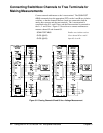
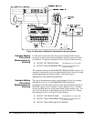
Figure 3-6. Connecting the Analog Bus and Digital Bus Cables
42 Using the HP E1351A/53A FET Multiplexer Modules Chapter 3