


Chapter 2
Configuring the HP E1351A/53A FET
Multiplexer Modules
Using This Chapter
This chapter shows how to configure the 16-Channel FET Multiplexer
Modules, how to connect external wiring and how to connect multimeters.
This chapter contains the following sections:
• Warnings and Cautions . . . . . . . . . . . . . . . . . . . . . . . . . . . . . Page 17
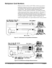
• Multiplexer Card Numbers . . . . . . . . . . . . . . . . . . . . . . . . . . Page 18
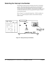
• Selecting the Interrupt Line Number . . . . . . . . . . . . . . . . . . . Page 20
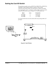
• Setting the Card ID Switch . . . . . . . . . . . . . . . . . . . . . . . . . . Page 21
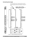
• Connecting User Inputs . . . . . . . . . . . . . . . . . . . . . . . . . . . . . Page 22
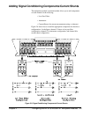
• Adding Signal Conditioning Components/Current
Shunts . . . . . . . . . . . . . . . . . . . . . . . . . . . . . . . . . . . . . . . Page 23
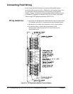
• Connecting Field Wiring . . . . . . . . . . . . . . . . . . . . . . . . . . . . Page 24
• Wiring a Terminal Module . . . . . . . . . . . . . . . . . . . . . . . . . . Page 25
• Connecting Multimeters and Signal Generators . . . . . . . . . . Page 26
• Analog Bus and Digital Bus Cables . . . . . . . . . . . . . . . . . . . Page 27
Warnings and Cautions
Warning SHOCK HAZARD. Only service-trained personnel who are
aware of the hazards involved should install, remove, or
configure the multiplexer modules. Before you install any
module, disconnect AC power from the mainframe and from
user wiring.
Caution MAXIMUM VOLTAGE/CURRENT. The maximum voltage that
may be applied between High (H), Low (L), and Guard (G)
terminals is 15 V dc or 10.6 V rms (15 V peak). The maximum
current is 1 mA per channel.
STATIC ELECTRICITY. Static electricity is a major cause of
component failure. To prevent damage to the electrical
components in the multiplexer module, observe anti-static
techniques whenever removing a module from the mainframe
or whenever working on a module.
Chapter 2 Configuring the HP E1351A/53A FET Multiplexer Modules 17