


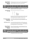
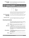
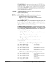
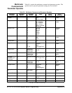
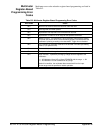
Table B-1. Multimeter Command and Parameter Opcodes (continued)
(1) Specified as a 2’s complement binary number. For three byte parameters <upper byte> = value shifted 16 bits to the
right (>>16), <middle byte> = value shifted 8 bits to the right (>>8), <lower byte> = value. For two byte parameters
<upper byte> = value shifted 8 bits to the right (>>8), <lower byte> = value & 0xFF.
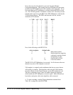
(2) Reading the Query Response register two times (16-bit number) or three times (24-bit number) returns in order; the
high byte, middle byte, and low byte.
(3) A parameter value of 0 sets infinite triggers per trigger arm.
(4) A parameter value of 0 sets infinite samples per trigger.
(5) Set when Sample Source is Timer.
(6) Used when Sample Source is Software. The first measurement of each burst occurs when the trigger signal is
received (e.g. Trigger Immediate). Subsequent measurements in the burst occur when Software Sample is written to the
Command register.
(7) Up to seven VXIbus TTLTrg trigger lines can be selected. 01 selects line 0, FF selects all lines.
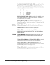
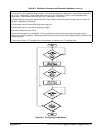
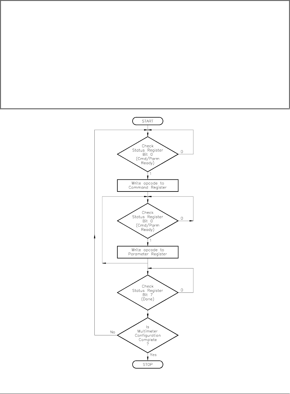
Figure B-3. Configuring the Multimeter
Appendix B HP E1351A/53A Register-Based Programming 97