


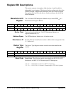


Now write once for each channel in your scan list to the Channel
Configuration Register. This register loads up a FIFO that will later rotate
each time the HP E1326B issues a VM complete on the digital bus. If you
have more than one FET multiplexer, you must load up the FIFOs on each
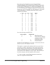
one. The VLD bit specifies if a channel is on this card. Note that you must
load the entire scan list to each HP E1351A FET Multiplexer, with only the
VLD bit being different. The FIFO, and hence the scan list, can be a
maximum of 512 channels.
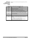
i.e. VLD A_D B_D C0-C1 D0-D3
0 1 1 volts 0
0 1 1 volts 1
0 1 1 volts 2
0 1 1 volts 3
0 1 1 volts 4
0 1 1 volts 5
0 1 1 volts 6
0 1 1 volts 7
0 1 1 volts 8
0 1 1 volts 9
0 1 1 volts 10
0 1 1 volts 11
0 1 1 volts 12
0 1 1 volts 13
0 1 1 volts 14
0 1 1 volts 15
Now, do the following to the HP E1351A:
write to register: decimal code:
4 8 Select direct control.
6 26 Enable digital bus triggering
continuous scanning, pointer
to beginning of scan.
4 0 Control back to DVM.
4 16 Close first channel.
The HP E1351A FET Multiplexer is now ready. It will advance to the next
channel every time a VM complete is received.
VM complete is a output from the multimeter that always occurs after an
A/D reading is complete. The digital bus cable wires the VM Complete
from the voltmeter to the Channel Advance on the FET multiplexer card.
The above command (to reg 6 value 26) enables digital bus triggering,
which enables the FET Multiplexer to use this signal. Make sure that you
have both a analog bus cable and a digital bus cable connected.
4. To start everything, issue the Trigger Immediate command from
Table B-1 on page 96, to the HP E1326B.
94 HP E1351A/53A Register-Based Programming Appendix B