


Example: Scanning
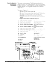
Using Scanning
Voltmeter
Configuration and
Digital Bus Triggering
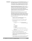
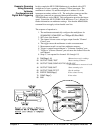
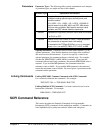
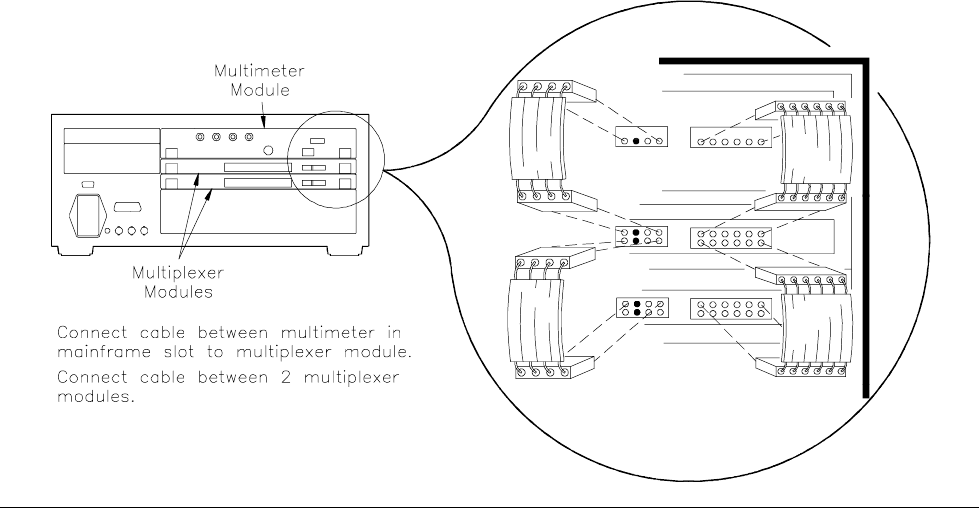
In this example the HP E1326B Multimeter is combined with a FET
multiplexer to form a scanning voltmeter VXIbus instrument. The
multimeter is address 24, and the multiplexer is address 25, so the
instrument secondary address is 03. The analog bus connector and the
digital bus connector are connected between the modules. The
TRIG:SOURce is set for DBUS. This configuration provides the fastest
speed. Consult the HP E1326B/E1411B Multimeter User’s Manual for
further information on multimeter settings. Note that the
ARM:COUNt
command does not apply to downloaded scan lists.
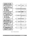
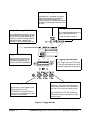
The sequence of operation is:
1. The multimeter automatically configures the multiplexer for
SCAN:MODE, SCAN:PORT and TRIGger:SOURce DBUS.
2.
INIT closes first channel.
3. The channel closure causes a trigger output from the "Channel
Closed" port.
4. The trigger causes the multimeter to make a measurement.
5. Measurement result is stored into multimeter memory.
6. Trigger is output from multimeter’s "Voltmeter Complete" port.
7. Trigger to "Advance Channel" port advances the channel list to the
next channel.
8. Steps 3-7 are repeated for channels 101 through 115.
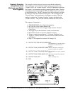
10 DIM Rdgs(1:16) !Dimension array for readings
20 OUTPUT 70903;"*RST" !Reset scanning voltmeter
30 OUTPUT 70903;"CONF:VOLT DC (@100:115)"
!Sets multimeter to measure dc volts
40 OUTPUT 70903;"INIT" !Starts scanning cycle
50 OUTPUT 70903;"FETC?" !Get the readings
60 ENTER 70903;Rdgs(*) !Place values in array
70 PRINT Rdgs(*) !Print values
80 END
Chapter 4 Understanding the HP E1351A/53A FET Multiplexer Modules 51