


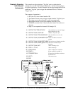
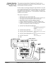
Example: Scanning
Using Stand-Alone
Multimeter and Digital
Bus Triggering
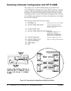
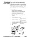
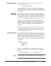
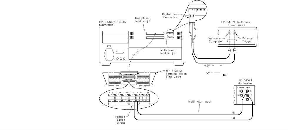
This example is similar to the previous one except that the multimeter’s
"External Trigger" and "Voltmeter Complete" ports are connected to the
"Channel Closed" and "Channel Advance" on the FET Multiplexer digital bus.
See Chapter 1 for information on making custom digital bus cables. Once the
scanning procedure has been initiated (
INIT), the channel closure is advanced
by the handshake lines. The
INIT command closes the first channel, and when
the channel is closed, the "Channel Closed" pulses. This is connected to the
"External Trigger" on the multimeter, which triggers a reading. When the
reading is complete, the "Voltmeter Complete" triggers, which pulses the
"Channel Advance". This procedure continues until the end of the scan list.
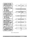
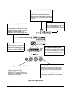
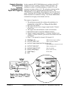
The sequence of operation is:
1.
TRIG:SOUR DBUS selects digital bus triggering.
2.
INIT (line 50) closes channel number 100.
3. The channel closure causes a trigger output from the "Channel
Closed" port.
4. The trigger causes the multimeter to make a measurement.
5. Measurement result is stored into multimeter memory.
6. Trigger is output from multimeter’s "Voltmeter Complete" port.
7. Trigger to "Advance Channel" port advances the channel list to the
next channel.
8. Steps 3-7 are repeated for channels 101 through 115.
10 OUTPUT 722;"TRIG EXT;DCV;MEM FIFO"
!Sets multimeter to external trigger
to measure dc volts and store
readings
20 OUTPUT 70914;"SCAN:PORT ABUS"!Routes channels to analog bus
connector and A tree terminal
30 OUTPUT 70914;"TRIG:SOUR DBUS"!Sets switchbox to receive external
triggers
40 OUTPUT 70914;"SCAN (@100:115)"!Selects the channel list (channels
100 to 115)
50 OUTPUT 70914;"INIT" !Starts scanning cycle
60 END
50 Understanding the HP E1351A/53A FET Multiplexer Modules Chapter 4