


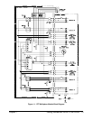
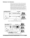

The logical addresses noted in Figures 2-1, 2-2, and 2-3 apply to modules
installed in an HP 75000 Series B Mainframe (HP Model Number
E1300A/E1301A) or in a mainframe with an HP E1405/1406 Command
Module. See the HP 75000 Series B Installation and Getting Started Guide
or the appropriate HP Command Module Manual for more information on
switchboxes and scanning voltmeter configurations, and logical addressing.
For uses in other systems or mainframes, see the appropriate manuals.
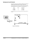
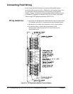
Setting the Address
Switch
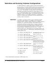
The logical address switch (LADDR) factory setting is 112. You may have
changed the switch setting during module installation. Valid address values are
from 1 to 255. Refer to the HP 75000 Series B System Installation and Getting
Started Guide or the appropriate HP Command Module Manual for addressing
information. Otherwise, refer to Figure 2-4 to reset the factory setting.
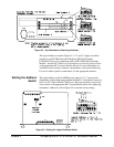
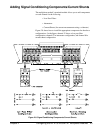
Figure 2-3. Card Numbers for Scanning Voltmeter
Figure 2-4. Setting the Logical Address Switch
Chapter 2 Configuring the HP E1351A/53A FET Multiplexer Modules 19