


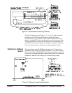
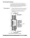
Connecting Field Wiring
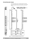
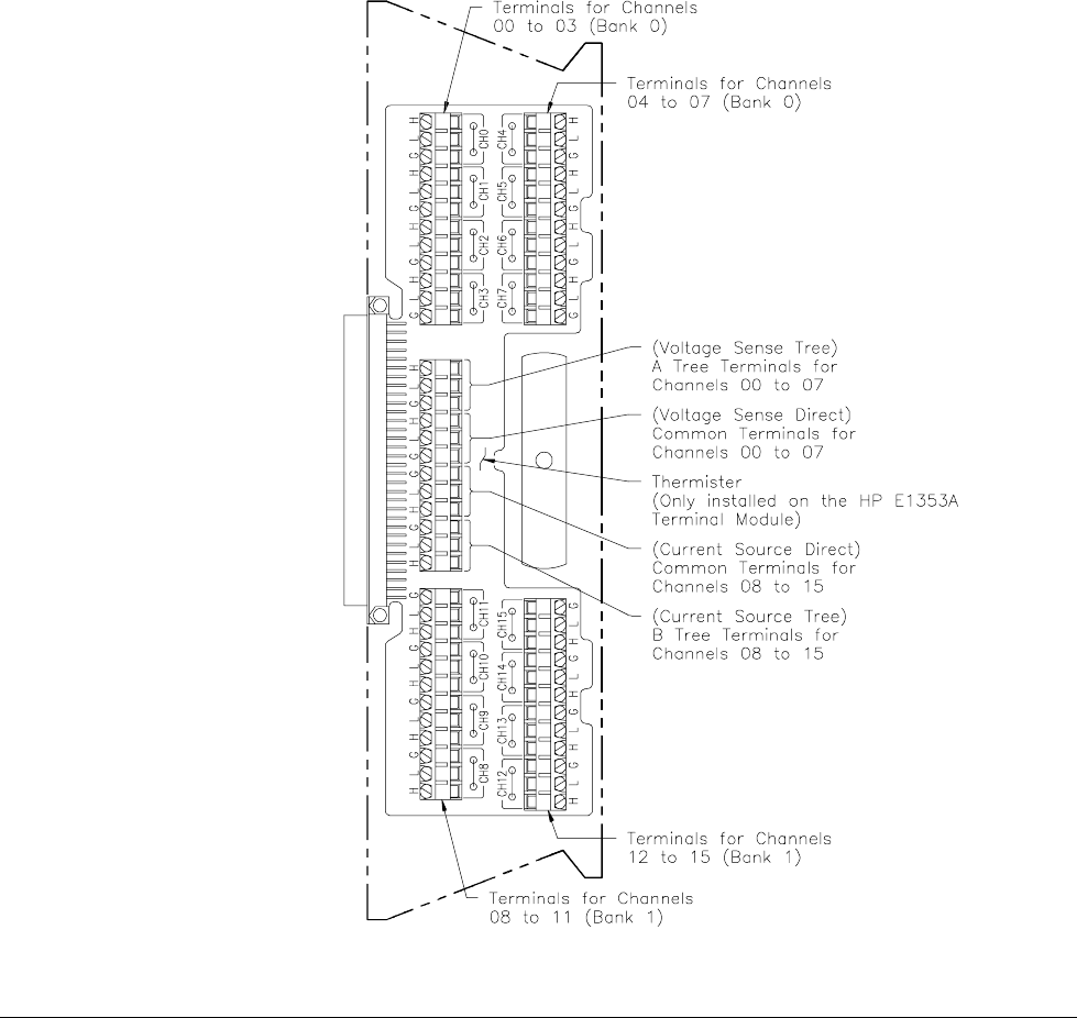
Leads for the individual channels are connected through the channel
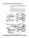
terminals on the terminal modules. Multimeters and signal generators can
be connected to the direct terminals or tree terminals on the terminal
modules. Figure 2-9 shows the terminal module channel terminals for the
16-Channel FET Multiplexer Module (HP E1351A) and the 16-Channel
Thermocouple FET Multiplexer Module (HP E1353A).
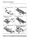
Wiring Guidelines • If possible, use shielded cables with the shields connected to the Guard
(G) terminals and to the low connection near the measurement point.
• Be sure the wires make good connections on the screw terminals.
• For thermocouples, connect the Guard terminal to the
thermocouple’s shield lead and the low connection near the
measurement point.
Figure 2-9. FET Multiplexer Modules Terminal Module
24 Configuring the HP E1351A/53A FET Multiplexer Modules Chapter 2