


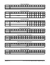
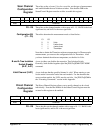

Scan Channel
Configuration
Register
These bits set the <channel_list> for a scan list, set the type of measurement
and enable/disable the tree isolation switches. Note that the DIR in the
Status/Control Register must be set false to enable this register.
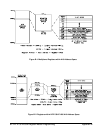
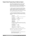
base + 0A
16
1514131211109876543210
Write VLD* A_D* B_D* C1 C0 X X X XXXXD3D2D1D0
Read Undefined
D3 - D0 These bits set the channel number, with a range of 0 - 15. Bit D0 is the least
significant bit, and bit D3 is the most significant.
Configuration Bit
(C1 - C0)
These bits determine the measurement mode as listed below:
C1 C0
0 0 Volts
0 1 2-wire ohms
1 1 4-wire ohms
1 0 Thermistor
Note that to obtain the Thermistor reference temperature for Thermocouple
measurements, you must set the configuration bits for Thermistor. After
you have obtained the reference temperature, set the bits for Volts.
B and A Tree Isolation
Switch Disable
(B-D*, A-D*)
A zero in either one disables the respective Tree Isolation Switch.
Generally, both disabled together equal the
[ROUTe:]SCAN:PORT NONE
command.
Valid Channel (VLD*) A zero indicates that the specified channel is valid. When entering a scan
list the entire list must be loaded into each module. For the channels that
are not on that module, the VLD* must be set false. See
[ROUTe:]SCAN in
the “Executing Commands” section in this Appendix.
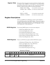
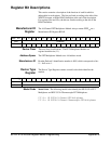
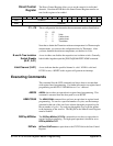
Direct Channel
Configuration
Register
The Direct Channel Register allows you to specify channels to be closed
individually. Note that the DIR bit in the Status/Control Register must be
set true for this register to be enabled.
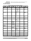
base + 0C
16
1514131211109876543210
Write Undefined XXXXD3D2D1D0
Read Undefined
D3 - D0 These data bits set the channel number with a range of 0 - 15. Bit D0 is the
least significant bit, and bit D3 is the most significant.
Appendix B HP E1351A/53A Register-Based Programming 89