


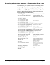

Scanning a Switchbox without a Downloaded Scan List
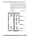
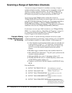
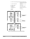
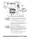
This example shows a FET switchbox connected to a multimeter with the
analog bus cable. The switchbox and multimeter are separate VXIbus
instruments. The multimeter has a secondary address of 03, and the
switchbox has a secondary address of 04. The multiplexer is triggered by
the
*TRG command. OUTPut ON is enabled, and the multimeter is
triggered by the
OUTPut ON trigger to its "External Trigger" port. The
following program illustrates the procedures:
10 DIM Rdgs(1:16) !Dimension array to store readings
20 OUTPUT 70903;"*RST;*OPC?" !Clear the multimeter; *OPC?
ensures reset is completed before
program continues
30 ENTER 70903;A
40 OUTPUT 70903;"*CLS"
50 OUTPUT 70904;"*RST" !Reset multiplexer
60 OUTPUT 70904;"*CLS"
70 OUTPUT 70903;"CONF:VOLT:DC 58.1"!Configure the multimeter
80 OUTPUT 70903;"TRIG:SOUR EXT" !External trigger source
90 OUTPUT 70903;"TRIG:COUN 16" !Set for 16 triggers
100 OUTPUT 70903;"INIT" !Initialize multimeter wait for
trigger
110 OUTPUT 70904;"TRIG:SOUR BUS" !Trigger on *TRG command
120 OUTPUT 70904;"SCAN:MODE VOLT"!Configure for voltage
130 OUTPUT 70904;"SCAN:PORT ABUS"!Enables analog bus
140 OUTPUT 70904;"SCAN (@100:115)"!Enter scan list
150 OUTPUT 70904;"OUTP ON" !Enable mainframe trig out port
160 OUTPUT 70904;"INIT" !Close first channel
170 FOR I = 1 TO 16 !16 channels
180 OUTPUT 70904;"*TRG" !Trigger for channel advance
190 WAIT .25 !Allow time for measurement
before next advance
200 NEXT I !Increment counter
210 OUTPUT 70903;"FETC?" !Multimeter retrieves readings
from mainframe memory when
scan completes
220 ENTER 70903;Rdgs(*) !Put readings in array
230 PRINT Rdgs(*) !Print
240 END
40 Using the HP E1351A/53A FET Multiplexer Modules Chapter 3