


INSTALLATION
A-5 A-5
DC-600
Return to Section TOC Return to Section TOC Return to Section TOC Return to Section TOC
Return to Master TOC Return to Master TOC Return to Master TOC Return to Master TOC
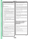
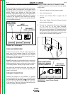
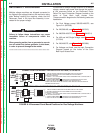
RECONNECT PROCEDURE
Multiple voltage machines are shipped connected to
the highest input voltage listed on the machine’s rating
plate. Before installing the machine, check that the
Reconnect Panel in the Input Box Assembly is con-
nected for the proper voltage.
Failure to follow these instructions can cause
immediate failure of components within the
machine.
When powering welder from a generator be sure to
turn off welder first, before generator is shut down,
in order to prevent damage to the welder
------------------------------
To reconnect a multiple voltage machine to a different
voltage, remove input power and change the position
of the reconnect board on the Reconnect Panel.
Follow The Input Connection Diagram located on the
inside of Case Back Input Access Door.
These connection diagrams for the following codes are
listed below.
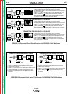
1. For Dual Voltage except 380/500-460/575, see
Figure A.4. (M15009)
2. For 220/380/460, see Figure A.5. (M15010)
3. For 380/500-460/575, see Figure A.6. (M15011)
4. For 460 and 440 Single Voltage, see Figure A.7.
(S17894)
5. For 230/460/575, see Figure A.8. (M15666)
6. For Voltages not listed, see the Input Connection
Diagram pasted on the inside of the Case
Back Input Access Door.
L3
L2
L1
LINK
LINES
INPUT
GND
H2
H1
H3
L3
L2
L1
LINK
LINES
INPUT
H3
H1
H2
GND
W
V
U
W
V
U
CONTACTOR
CRI
CRI
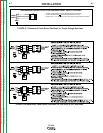
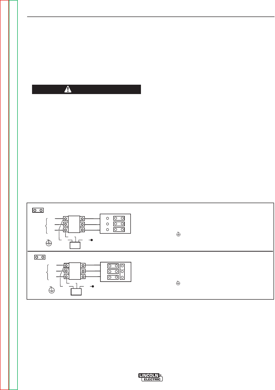
CONNECTION FOR HIGHEST RATING PLATE VOLTAGE, 50 OR 60 HZ.
CONNECTION FOR LOWEST RATING PLATE VOLTAGE, 50 OR 60 HZ.
CTOR
1. TURN OFF THE INPUT POWER USING THE DISCONNECT SWITCH AT THE FUSE BOX
2. DISCONNECT AND INSULATE THE H2 LEAD TERMINAL WITH TAPE TO PROVIDE AT
LEAST 600 VOLT INSULATION.
3. CONNECT L1, L2 & L3 INPUT SUPPLY LINES H1 AND H3 TRANSFORMER LEADS TO THE INPUT SIDE OF
THE CRI CONTACTOR AS SHOWN.
4. CONNECT TERMINAL MARKED TO GROUND PER LOCAL AND NATIONAL ELECTRIC CODES.
5. MOUNT THE LINKS IN THE POSITIONS SHOWN WITH THE PROVIDED HEX NUTS,
DOUBLE UP THE LINKS IN TWO OF THE POSITIONS TO SAVE THEM FOR FUTURE USE. SECURE THE
REMAINING HEX NUTS IN PLACE.
1. TURN OFF THE INPUT POWER USING THE DISCONNECT SWITCH AT THE FUSE BOX
2. DISCONNECT AND INSULATE THE H3 LEAD TERMINAL WITH TAPE TO PROVIDE AT
LEAST 600 VOLT INSULATION.
3. CONNECT L1, L2 & L3 INPUT SUPPLY LINES H1 AND H2 TRANSFORMER LEADS TO THE INPUT SIDE OF
THE CRI CONTACTOR AS SHOWN.
4. CONNECT TERMINAL MARKED TO GROUND PER LOCAL AND NATIONAL ELECTRIC CODES.
5. MOUNT THE LINKS IN THE POSITIONS SHOWN WITH THE PROVIDED HEX NUTS.
PILOT
TRANSF.
PILOT
TRANSF.
FIGURE A.4-Reconnect Panel Board Positions for Dual Voltage Machines
CAUTION