


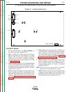
OUTPUT PROBLEMS
Observe Safety Guidelines detailed in the beginning of this manual.
PROBLEMS
(SYMPTOMS)
POSSIBLE AREAS OF
MISADJUSTMENT(S)
RECOMMENDED
COURSE OF ACTION
If for any reason you do not understand the test procedures or are unable to perform the tests/repairs safely,
contact the Lincoln Electric Service Department for technical troubleshooting assistance before you proceed.
Call 1-888-935-3877.
CAUTION
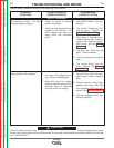
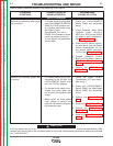
Input contactor pulls in when
ON/OFF Switch is closed but imme-
diately drops out.
1. Make sure input line voltage
matches machine rating and the
reconnect panel is connected
correctly for the line voltage.
Remove all weld cables and
external wires attached to termi-
nal strip and the 14pin MS con-
nector and make sure the
Output Terminals Switch is in
the REMOTE position.
2. If the problem persists after per-
forming step 1 the problem is in
the DC600.
1. If contactor (CR1) functions
correctly with the cables
removed there may be a fault in
the control cables or the wire
feeder. See Protective Devices
and Shutdown Circuits.
2. Check internal remote control
circuit (leads 75, 76 and 77)
including the Output Terminals
Switch (S3) and the Output
Control (R1) for grounds or
shorts. See the Wiring
Diagram.
4. The Control Board may be
faulty. See the PC Board
Troubleshooting Guide.
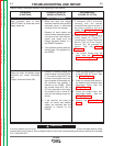
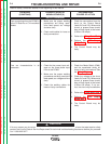
Machine shuts off (input contactor
drops out) when the welder output
terminals are made electrically
"hot".
(Output Terminals Switch ON).
1. Remove all welding cables and
control cables from the DC 600.
If the machine does NOT shut
off and normal open circuit volt-
age is present at the welder out-
put terminals the problem is
external to the DC600. Either
the remote leads #75, #76 or
#77 are grounded to the nega-
tive output circuit or there is a
short on the welding output ter-
minals.
2. If the machine still shuts off
when all control and welding
cables are removed then the
problem is internal to the
DC600.
1. Check for grounds and or shorts
in the #75, #76, #77 circuit. See
the Wiring Diagram.
2. Check for grounds and shorts in
the welder output terminals and
associated leads. See the
Wiring Diagram.
3. Check the output shunt and
associated leads. See the
Wiring Diagram.
4. Perform the Con trol Board
Test.
TROUBLESHOOTING AND REPAIR
F-5 F-5
DC-600
Return to Section TOC Return to Section TOC Return to Section TOC Return to Section TOC
Return to Master TOC Return to Master TOC Return to Master TOC Return to Master TOC