


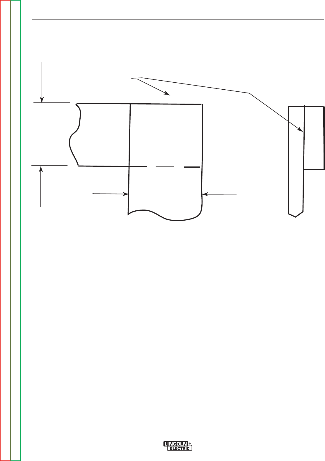
WELD
W
W
XXXXXXXXXXX
XXXXXXXXXXX
XXXXXXXXXXX
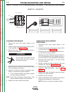
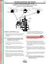
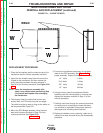
FIGURE F.21 – CHOKE TIG WELD
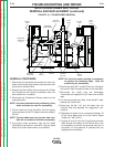
MAIN TRANSFORMER AND CHOKE
REMOVAL AND REPLACEMENT (continued)
REPLACEMENT PROCEDURE
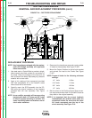
1. Place the flat washers and the choke on top of the
transformer and the lift bale assembly over both.
2. Install the four thread cutting bolts that mount the
lift bale to the transformer and then replace the
choke mounting hardware that was removed in
Step 20 of the removal procedure. See Figure F.20.
NOTE: Cover the transformer assembly with
‘damp’ shop cloths before performing Step
3 to prevent weld spatter from damaging
the transformer.
3. Thouroughly clean the choke lead and the sec-
ondary lead and TIG weld along the two edges.
The welds must be at least as long as the widths of
the two pieces See Figure F.21.
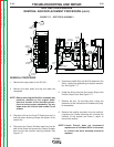
4. Mount the SCR Bridge assembly using the hard-
ware and insulators removed in Step 18 of the
removal procedure. See Figure F.18.
5. Connect the transformer secondary and snubber
leads to the SCR assembly. See Figure F.19 for
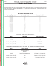
proper assembly. Torque all bolts per the following:
1/4” bolts 6 ft/lbs.
5/16” bolts 11 ft/lbs.
3/8” bolts 19 ft/lbs.
1/2” bolts 45 ft/lbs.
6. Using the hoist, place the transformer/lift bale
assembly over the mounting bolts in the base and
replace the hardware removed in Step 21 of the
removal procedure.
7. Carefully back track through the removal procedure,
re-routing and re-connecting the leads that were
cut, removed or separated using proper electrical
techniques and insulating where required.
8. Replace the baffles and any sleeving, cable ties or
sealants that were removed during the disassembly
procedure.
TROUBLESHOOTING AND REPAIR
F-48 F-48
DC-600
Return to Section TOC Return to Section TOC Return to Section TOC Return to Section TOC
Retur n to Master TOC Return to Master TOC Return to Master TOC Return to Master TOC