


THEORY OF OPERATION
E-3 E-3
DC-600
Return to Section TOC Return to Section TOC Return to Section TOC Return to Section TOC
Return to Master TOC Return to Master TOC Return to Master TOC Return to Master TOC
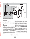
FIRING CIRCUIT, CONTROL CIR-
CUIT AND RECTIFICATION
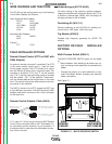
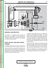
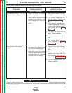
RECTIFICATION
The “neutrals” of the welding secondary windings in the
main transformer are connected together, and the six
starts are connected to the six Silicon Controlled
Rectifier (SCR) assemblies to form a six-phase output.
This six-phase AC output from the main transformer
secondary is rectified and controlled by the SCR
bridge.
FIRING BOARD
The firing board is powered by the three-phase 32vac
transformer windings. Each phase provides two firing
pulses, one for each of the two SCRs controlled by that
phase. When a gate firing enable*(trigger) signal is
received, the firing circuit supplies the proper amount
of energy to the gates of the power SCRs. When this
gate firing signal is applied at the correct time, the SCR
will turn ON. The amount of ON time versus OFF time
determines the output of the machine. See SCR
Operation. At the same time the latching resistor is
connected across the machine’s output circuit. The
latching resistor provides a pre-load for the SCR bridge
so the SCR’s will stay activated providing open circuit
voltage (OCV).
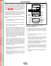
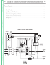
FIGURE E.2 - FIRING BOARD,CONTROL BOARD AND RECTIFICATION
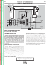
CONTROL BOARD
The control board receives current feedback informa-
tion from the shunt and voltage feedback information
from the choke and welding output terminals. This
feedback information is processed on the control
board. The control board compares the commands of
the mode switch, the output control potentiometer (or
remote control device) and the arc force control with
the feedback information and sends the appropriate
output control signal to the firing board. In the event of
a “fault condition,” the control board de-activates the
fault relay (CR2). See Protective Devices and Shut
Down Circuits.
An output choke is connected between the neutral con-
nection of the main transformer secondaries and the
negative output terminal. This large inductor stores
energy, and provides current filtering for the welding
output of the DC-600.
*Triggering is accomplished by a connection of lead
#2 & #4 by way of the Output Terminal Switch or by a
remote signal from a wire feeder. The 2 to 4 closure
is indicated by LED10 on the firing Board and LED 6
on the Control Board.
CONTROL
TRANSFORMER
R
E
C
O
N
N
E
C
T
CONTACTOR
FAULTPROTECTION
115VAC
MAIN
TRANSFORMER
CONTROL
BOARD
SHUNT
OUTPUT
CONTROL
MODE
SWITCH
POSITIVE
TERMINAL
NEGATIVE
TERMINAL
LATCHING
RESISTOR
F
E
E
D
B
A
C
K
F
E
E
D
B
A
C
K
SCR BRIDGE
115VAC
42VAC
T
E
R
M
I
N
A
L
S
T
R
I
P
FIRING
BOARD
CR2
CR1
CHOKE
14-pin
Amphenol
115VAC
Receptacle
Fan
Motor
32VAC
32VAC
32VAC
SIGNAL
G
A
T
E
S
I
G
N
A
L
OUTPUT
CONTROL
Secondary
Thermostat
Primary
Theromstat
1CRCoil
w
Pilot
Light
•
•
OUTPUT
TERMINAL
SWITCH
POWER
SWITCH
•
TERMINAL
STRIP 1
OUTPUT
CONTROL
SWITCH
2
115VAC
NOTE: Unshaded areas of Block Logic
Diagram are the subject of discussion