


INSTALLATION
A-9 A-9
DC-600
Return to Section TOC Return to Section TOC Return to Section TOC Return to Section TOC
Return to Master TOC Return to Master TOC Return to Master TOC Return to Master TOC
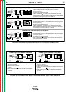
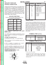
TERMINAL STRIPS
Terminal strips are available behind the cover on the
case front to connect wire feeder control cables that do
not have a 14 Pin MS-type connector. These terminals
supply the connections as shown in the following
Terminal Strip charts. NOTE:There are two work sense
lead connection points on the terminal strip. Connect
both the work sense lead #21 from the 14 pin connec-
tor and #21 lead of the control cable to “-21” when
welding positive polarity or to “+21” when welding neg-
ative polarity.
TERMINAL STRIP 1 (T.S.1)
TERMINAL STRIP 2 (T.S.2)
Lead No. Function
75 Output Control
76 Output Control
77 Output Control
Lead No. Function
+21
Work Connection (Electrode Negative)
-21
Work Connection (Electrode Positive)
2
41 42 VAC
4 Trigger Circuit
2 Trigger Circuit
31 115 VAC
1
32 115 VAC
1
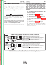
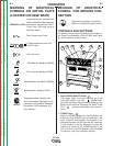
AUXILIARY POWER AND
CONTROL CONNECTIONS
Located at the left side of the front of the welder behind
a hinged cover is a 115VAC duplex receptacle for aux-
iliary power (60 Hertz Models only). On the right side of
the case front is a 14 Pin MS type receptacle for con-
nection of auxiliary equipment such as wire feeders.
Also, terminal strips with 115VAC and connections for
auxiliary equipment are located behind the hinged
access panel on the right side of the case front. (see
Auxiliary Power Table for details)
115VAC DUPLEX RECEPTACLE (60 HERTZ
MODELS ONLY)
The 115VAC duplex receptacle is protected by a circuit
breaker located on the nameplate. The receptacle is a
NEMA 5-15R.
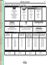
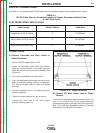
AUXILIARY POWER TABLE
Voltage and Circuit Breaker Ratings at Auxiliary Power
Connections for Various Models
Auxiliary 60 Hz 50/60 Hz
Power Models Models
Connections
At Duplex 115V 15A No Duplex
Receptacle
Terminal strip 115V 15A 115V 15A
terminals31&32
MS-Receptacle 115V 15A 115V 15A
pinsA&J
MS-Receptacle 42V 10A 42V 10A
pinsI&K
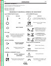
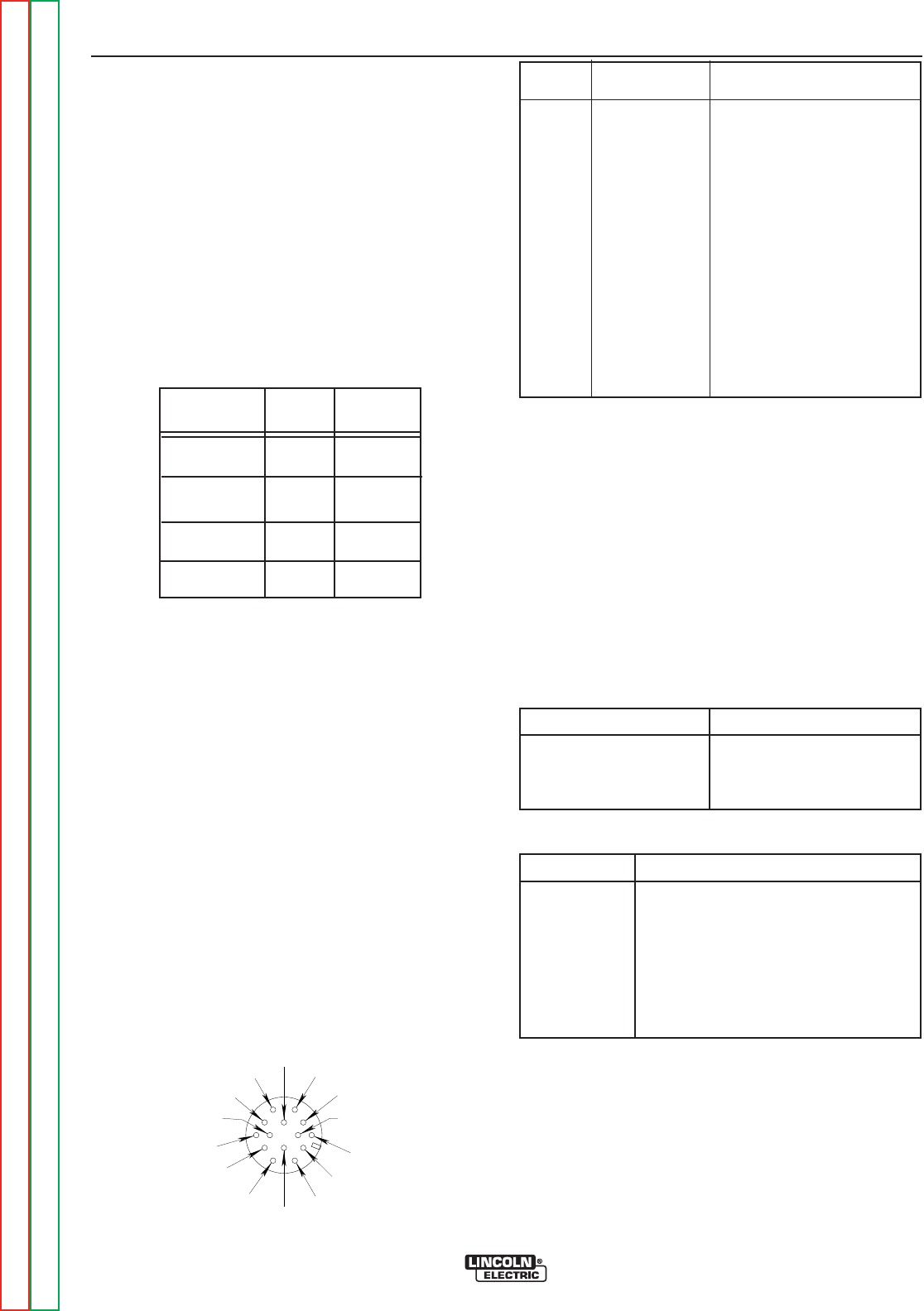
PIN LEAD NO. FUNCTION
A 32 115 VAC
B GND Chassis Connection
C 2 Trigger Circuit
D 4 Trigger Circuit
E 77 Output Control
F 76 Output Control
G 75 Output Control
H 21 Work Sense Connection
2
I41 42VAC
J 31 115 VAC
1.
K42 42VAC
L --- ---
M --- ---
N --- ---
F=76
G=75
H=21
I=41
J=31
K=42
A=32
B=GND
C=2
D=4
E=77
LN
M
1.
115VAC circuit is on all models.
2.
As shipped from the factory Lead #21 from the 14 Pin connector is
connected to “-21” on the terminal strip (T.S.2).
This is the configuration for positive welding. If welding negative
polarity, connect lead #21 to the “+21” connection point on the ter-
minal strip (T.S.2).
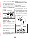
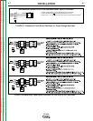
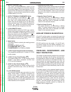
14 PIN MS TYPE RECEPTACLE
(For MS3106A-20-27PX Plug. L.E.C. Part #S12020-32)
Refer to the figure A.10 for the available circuits in the
14 pin receptacle.
42 VAC is available at receptacle pins I and K.
A 10 amp circuit breaker protects this circuit.
115 VAC is available at receptacle pins A and J (All
Models). A 15 amp circuit breaker protects this circuit.
Note that the 42 VAC and 115 VAC circuits are electri-
cally isolated from each other.
FIGURE A.10 FRONT VIEW OF 14-PIN
CONNECTOR RECEPTACLE