


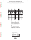
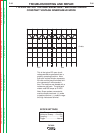
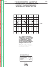
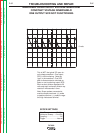

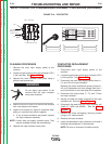
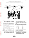

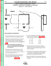

"C" LEAD, RED
(6 PLACES)
"A" LEAD, WHITE
(6 PLACES)
GATE LEAD
CONNECTOR
OUTPUT
SNUBBER
A
A
A
A
A
A
A
A
A
A
A
A
A
A
A
A
LEFT SIDE
OF CHOKE
TO LEFT SIDE
OF CHOKE
OUTPUT
SHUNT
210
215
MOUNTING
BOLTS (4)
SECONDARY
LEAD (6 PLACES)
BUSHING
CONNECTION
STRAP
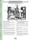
FIGURE F.17 – RECTIFIER ASSEMBLY
SCR RECTIFIER BRIDGE
REMOVAL AND REPLACEMENT PROCEDURE (cont.)
REMOVAL PROCEDURE
1. Remove the input power to the DC-600.
2. Remove the case sides and top and lower the
nameplate.
NOTE: Before removing the Rectifier Assembly pay
particular attention to the original place-
ment and location of the electrical connec-
tions to assure proper reassembly. Tag any
leads where the Lincoln lead number is not
evident.
3. Disconect J4 from the firing PC Board and push it
and the plastic bushing through the bottom of the
control box.
4. Disconnect the Output Snubber lead from the left
side of the Choke and remove the Output Snubber
from the left side rectifier mounting bracket. See
Figure F.17.
5. Disconnect the #210(2) and #215(5) leads from the
Shunt, noting their positioning for proper reassem-
bly. See Figure F.17.
6. Unbolt the Shunt from the Connection Strap at the
Positive Output Stud. See Figure F.17.
7. Remove the four (4) mounting bolts, noting the
placement of the insulators and hardware for prop-
er reassembly.
8. Remove the rectifier assembly from the machine.
Loosening the Choke mountings will increase the
flexibility of the bracket and make it easier to
remove the rectifier.
NOTE: Lincoln Electric does not recommend
replacement of individual SCRs. In the event
of a failure, the entire assembly should be
replaced.
TROUBLESHOOTING AND REPAIR
F-42 F-42
DC-600
Return to Section TOC Return to Section TOC Return to Section TOC Return to Section TOC
Retur n to Master TOC Return to Master TOC Return to Master TOC Return to Master TOC