


THEORY OF OPERATION
E-4 E-4
DC-600
Return to Section TOC Return to Section TOC Return to Section TOC Return to Section TOC
Return to Master TOC Return to Master TOC Return to Master TOC Return to Master TOC
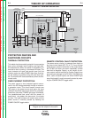
PROTECTIVE DEVICES AND
SHUTDOWN CIRCUITS
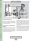
THERMAL PROTECTION
This welder has thermostatic protection from excessive
duty cycles, overloads, loss of cooling, and high ambi-
ent temperatures. When the welder is subjected to an
overload or loss of cooling, a thermostat will open. The
input contactor will open and remain open until the
machine cools; the white POWER light stays illuminat-
ed. No welding is possible during this cool down peri-
od. The machine will reset automatically when the ther-
mostat cools.
OVER CURRENT PROTECTION
The power source is also protected against overcur-
rents in the SCR bridge assembly through an electron-
ic protection circuit. This circuit senses currents over
780 amps on the power source and opens the input
contactor should the overcurrent remain for a predeter-
mined time (the white POWER light stays illuminated).
The predetermined time varies with the amount of
overcurrent; the greater the overcurrent, the shorter
the time. The input contactor will remain open until the
power source is manually started by resetting the
POWER ON/OFF toggle switch
.
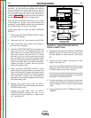
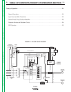
FIGURE E.2 - GENERAL DISCRIPTION
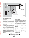
REMOTE CONTROL FAULT PROTECTION
The power source circuitry is protected from faults on
the control circuit leads (#75, 76, or 77). If any of these
leads become common with either of the output leads,
the DC-600 will either shut down completely (control
lead fault to Negative Output), or will remain at mini-
mum output (control lead fault to Positive Output) thus
preventing any damage to the DC-600. If DC-600 shuts
down, (input contactor opens and white POWER light
stays illuminated) it must be manually started by reset-
ting the POWER ON/OFF toggle switch.
CONTROL
TRANSFORMER
R
E
C
O
N
N
E
C
T
CONTACTOR
FAULTPROTECTION
115VAC
MAIN
TRANSFORMER
CONTROL
BOARD
SHUNT
OUTPUT
CONTROL
MODE
SWITCH
POSITIVE
TERMINAL
NEGATIVE
TERMINAL
LATCHING
RESISTOR
F
E
E
D
B
A
C
K
F
E
E
D
B
A
C
K
SCR BRIDGE
115VAC
42VAC
T
E
R
M
I
N
A
L
S
T
R
I
P
FIRING
BOARD
CR2
CR1
CHOKE
14-pin
Amphenol
115VAC
Receptacle
Fan
Motor
32VAC
32VAC
32VAC
SIGNAL
G
A
T
E
S
I
G
N
A
L
OUTPUT
CONTROL
Secondary
Thermostat
Primary
Theromstat
1CRCoil
w
Pilot
Light
•
•
OUTPUT
TERMINAL
SWITCH
POWER
SWITCH
•
TERMINAL
STRIP 1
OUTPUT
CONTROL
SWITCH
2
115VAC
NOTE: Unshaded areas of Block Logic
Diagram are the subject of discussion