


OPERATION
B-5 B-5
DC-600
Return to Section TOC Return to Section TOC Return to Section TOC Return to Section TOC
Return to Master TOC Return to Master TOC Return to Master TOC Return to Master TOC
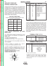
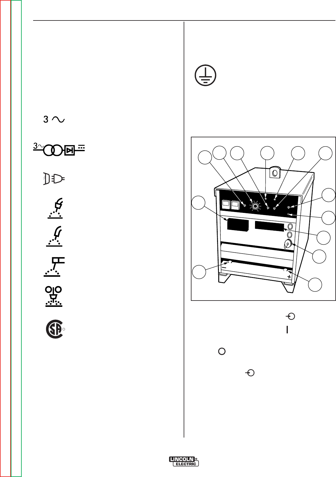
CONTROLS AND SETTINGS
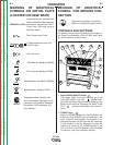
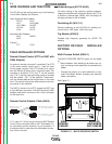
All operator controls and adjustments are located on
the Case Front Assembly of the DC-600. See Figure
B.1 for the location of each control.
FIGURE B.1 - CONTROL PANEL KEYS
1
2
3
4
5
6
7
8
9
10
DC-600
13
12
7
5
11
2
1
49
8
6
3
10
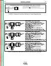
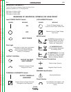
3 Phase transformer with recti-
fied DC output
Line Connection
Three Phase Input Power
Designates welder complies with
National Electrical Manufacturers
Association requirements EW 1
Class I with 100% duty cycle at
600Amps output.
Designates welder complies with
both Underwriters Laboratories (UL)
standards and Canadian Standards
Association (CSA) standards. (60
Hertz Models)
Gas Metal Arc Welding (GMAW)
Flux Cored Arc Welding (FCAW)
MEANING OF GRAPHICAL
SYMBOLS ON RATING PLATE
(LOCATED ON CASE BACK)
NEMA EW 1 (100%)
Shielded Metal Arc Welding (SMAW)
Submerged Arc Welding (SAW)
MEANING OF GRAPHICAL
SYMBOL FOR GROUND CON-
NECTION
Signifies the equipment connection
point for the protective earth ground
R
NRTL/C
1. Input POWER ON/OFF Switch
This toggle switch turns the machine on or off.
Putting the switch in the ON “ ” position ener-
gizes the machine’s input contactor applying input
power to the machine. Switching the switch to the
OFF “ ” position de-energizes the input con-
tactor.
2. POWER Light
When the POWER switch is in the ON position the
machine’s white POWER light will illuminate. If the
input contactor de-energizes the machine in an
abnormal situation the pilot light will still illuminate.
In this situation it may be necessary to reset the
machine by switching the POWER switch to the
OFF and then to the ON position. (See Overload,
Overcurrent, and Fault Protection Section)