


TROUBLESHOOTING AND REPAIR
F-49 F-49
DC-600
Return to Section TOC Return to Section TOC Return to Section TOC Return to Section TOC
Retur n to Master TOC Return to Master TOC Return to Master TOC Return to Master TOC
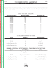
RETEST AFTER REPAIR
Should a machine under test be rejected for any reason requiring the removal of any mechanical part that could
affect the machine’s electrical characteristics, or if any electrical components are repaired or replaced, the
machine must be retested.
INPUT IDLE AMPS AND WATTS
Input volts/Phase/Hertz Maximum Idle Amps Maximum Idle KW
208/3/60 11.0 1.0
230/3/60 10.0 1.0
380/3/60 6.0 1.0
416/3/60 5.5 1.0
460/3/60 5.0 1.0
550/3/60 4.2. 1.0
575/3/60 4.0 1.0
200/3/50 21.0 1.3
220/3/50 19.1 1.3
230/3/50 18.3 1.3
380/3/50 11.0 1.3
400/3/50 10.5 1.3
415/3/50 10.1 1.3
440/3/50 9.6 1.3
500/3/50 8.4 1.3
550/3/50 7.7 1.3
MAXIMUM OPEN CIRCUIT VOLTAGES
Mode Input Hertz Open Circuit Volts
CC Stick 60 66/70
CV MIG 60 44/47
Auxiliary Output (#31-#32) 60 122/128 VAC
Auxiliary Output (#41-#42) 60 44/48 VAC
MINIMUM ACCEPTABLE OUTPUT VOLTAGE - AT MAXIMUM OUTPUT SETTINGS
Mode Control Settings Load
CC Stick Output Control at Maximum 815 Amps @ 44.0 Volts (Min)
Arc Force Control at
Minimum
CV MIG Output Control at Maximum 815 Amps @ 44.0 Volts (Min)
Auxiliary Output (#31-#32) N/A 5 Amps @ 120/126 VAC (Min)
Auxiliary Output (#41-#42) N/A 5 Amps #41/45 VAC (Min)