


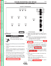

A
Power
Switch
Secondary
Thermostat
Control
Transformer
L3 T3
L2 T2
L1 T1
H2, H3or H4(see Input Diagram)
H1
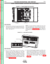
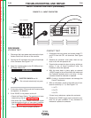
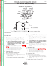
FIGURE F.12 - CONTROL TRANSFORMER
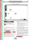
CONTROL TRANSFORMER TEST (continued)
PROCEDURE
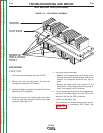
1. With the Input Power OFF, remove the case top,
right side panel and the input access door. The
Control Transformer is located on the back of the
Input Box. See Figure F.12.
• The Primary Leads (black)are routed through the
Input Box and two of them (depending on input
voltage) are connected to L1 and L3 of the Input
Contactor. Any unused leads are to be insulated
and taped.
• The Secondary leads (red) are connected to the
Power Switch (X1) and the Secondary
Thermostat (X2).
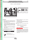
2. Connect the Input Power and make certain that
rated voltage is present at L1 and L3.
NOTE: The DC-600 does not need be to turned ON.
ELECTRIC SHOCK can kill.
• Do not touch electrically hot parts.
3. Measure the voltage from X1 to X2. It should be
approximately 120VAC.
4. If this reading is incorrect check the connections on
the Primary and Secondary lads. If OK, the trans-
former may be defective.
NOTE: Common causes of control transformer failure
are;
• Improper connection of the Primary leads.
• A defective (shorted) Input Contactor coil.
IMPORTANT
Before installing a new transformer perform the
Input Contactor Test.
Carefully read and follow the Input Connection
instructions located on the Input Access Door
when installing the new transformer. If you do not
have those instructions, call The Lincoln Electric
Co. (1-888-935-3877) with the Code Number of the
DC-600 and the instructions can be faxed or e-
mailed to you.
TROUBLESHOOTING AND REPAIR
F-26 F-26
DC-600
Return to Section TOC Return to Section TOC Return to Section TOC Return to Section TOC
Return to Master TOC Return to Master TOC Return to Master TOC Return to Master TOC
WARNING