


A
A
A
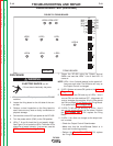
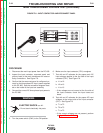
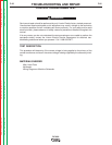
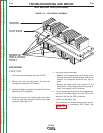
SECONDARY LEADS
(6 PLACES)
COMMONBUSS
FIGURE F.9 – TRANSFORMER SECONDARIES
MAIN TRANSFORMER VOLTAGE TEST (continued)
PROCEDURE
9. Test with an AC voltmeter for approximately 55 VAC
from each of the six main transformer secondary
leads to the common bus connected to the output
choke. See Figure F.9.
NOTE: All of the secondary voltages will vary if the
input line voltages vary. If any one or more of the volt-
age checks are incorrect, check for loose or faulty con-
nections. See the Wiring Diagram. If the leads and
connections are OK, the main transformer may be
faulty.
TROUBLESHOOTING AND REPAIR
F-23 F-23
DC-600
Return to Section TOC Return to Section TOC Return to Section TOC Return to Section TOC
Return to Master TOC Return to Master TOC Return to Master TOC Return to Master TOC
1
2
3
4
5
6
7
8
9
10
DC-600
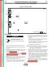
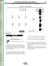
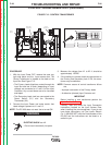
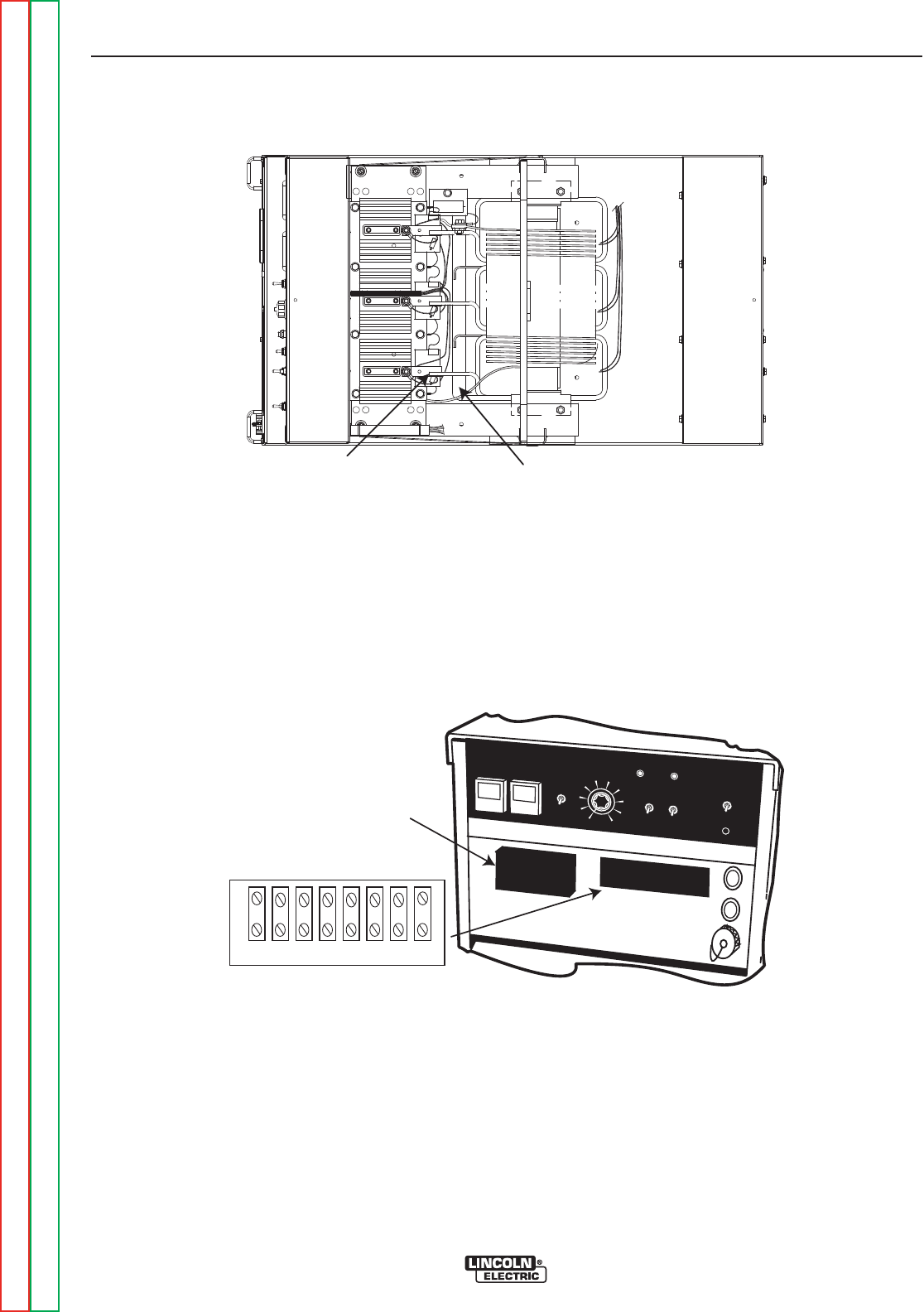
21-21+ 41 4 2 31 32
TS 2
RECEPTACLE
PROCEDURE
10. Test for 120 VAC between leads #31 and #32 on
terminal strip TS-2. See Figure F.10. 120 VAC
should also be present at the receptacle. If the cor-
rect voltage is not present, make sure the 20 amp
circuit breaker is not tripped or faulty. Also check
the wiring between the main transformer, the termi-
nal strip, the circuit breaker and the receptacle. See
the Wiring Diagram.
12. Test for 42 VAC between leads #41 and #2 on the
terminal strip. See Figure F.10. If the correct volt-
age is not present, make sure the 10 amp circuit
breaker is not tripped or faulty. Also check the
wiring between the main transformer, the terminal
strip, and the circuit breaker. See the Wiring
Diagram.
FIGURE F.10 – AUXILIARY VOLTAGES