


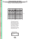

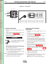

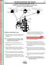

Thread Forming Screw
Plain Washer
Insulator
Insulator
Insulator
Plain Washer
Lock Washer
5/16-18 Hex Nut
Rectifer Mounting
Bracket
Bridge Mounting
Bracket
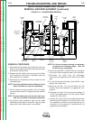
Fig. 18 ‘A’
Fig. 18 ‘B’
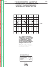
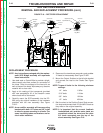
Transformer
Secondary Lead
‘A’ Lead from
Snubber
Heat Sink
Negative Output Lead
Output Snubber Lead
Choke Lead
Lock Washer
3/8-16 Hex Nut
3/8-16 x 1 Cap Screw
Plain Washers (2)
Fig18‘C’
A
A
A
A
A
A
A
A
A
A
A
A
A
A
A
A
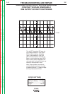
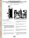
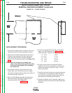
OUTPUT
SHUNT
210
215
MOUNTING
BOLTS (4)
SECONDARY
LEAD CONNECTION
(6 PLACES)
CONNECTION
STRAP
OUTPUT
SNUBBER
CONNECTION
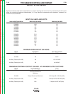
FIGURE F.18 – RECTIFIER REPLACEMENT
SCR RECTIFIER BRIDGE
REMOVAL AND REPLACEMENT PROCEDURE (cont.)
REPLACEMENT PROCEDURE
NOTE: Any instructions packaged with the replace-
ment SCR Bridge assembly will supercede
these instructions.
1. Use steel wool or Scotch-Brite to provide a bright,
clean,smooth paint-free surface for connection of
the leads. Clean the surfaces of the heat sink as
well as those of the leads. Wipe away any abrasive
material with a clean cloth.
2. Apply a thin coating of joint compound (provided
with new assembly)to all of the heatsink areas
where leads will be connected.
3. Carefully mount the SCR assembly into the DC-
600 using the original hardware or the hardware
provided with the new assembly. See Figure
F.18’A’.
NOTE: A new rectifier assembly will have mounting
brackets with both 1/2” holes and 3/8” holes
to allow for proper mounting in all units.The
spare insulating tubes and washers are for
use in older machines.
4. Reconnect the transformer secondary and snubber
‘A’ leads to the assembly. See Figure F.18’B’.
5. Mount the Output Snubber to the left side bracket
and connect the lead to the Choke. See Figure
F.18’C’.
NOTE: Torque all bolts for the following minimum
settings:
1/4” bolts 6 ft/lbs.
5/16” bolts 11 ft/lbs.
3/8” bolts 19 ft/lbs.
1/2” bolts 45 ft/lbs.
6. Bolt the shunt to the Positive Output Stud connec-
tion strap and connect the # 210 and #215 leads as
they were on the original assembly.
NOTE: It is important that the current feedback
leads(twisted pair) and the meter leads are
connected across the shunt and the other
215 leads connected near the top of the
shunt assembly. See Figure F.18.
TROUBLESHOOTING AND REPAIR
F-43 F-43
DC-600
Return to Section TOC Return to Section TOC Return to Section TOC Return to Section TOC
Retur n to Master TOC Return to Master TOC Return to Master TOC Return to Master TOC